
Test device for hydraulic multi-way valve of tractor and test method thereof

A test device and multi-way valve technology, applied in the direction of fluid pressure actuation device, fluid pressure actuation system test, mechanical equipment, etc., can solve problems such as poor cleanliness, damage to the matching sealing surface, difficulty in valve stem reset, etc., to achieve Reasonable design, high yield rate, and simple structure

Pending Publication Date: 2020-08-07
FIRST TRACTOR
View PDF0 Cites 2 Cited by
  • Summary
  • Abstract
  • Description
  • Claims
  • Application Information

AI Technical Summary

Problems solved by technology

The main reasons are concentrated in the manufacturing process control: 1. The gap between the valve stem and the valve body is relatively large. Long-term use or unclean oil will accelerate the wear of the valve stem and valve body, destroy the matching sealing surface, and cause internal leakage. Oil
2. If the solid torque of the bolts is different, it will cause the valve body to warp
In addition, the joint surface of the valve body is damaged or the O-ring is damaged during assembly. Under the action of oil pressure, leakage occurs between the valve bodies.
3. If the cleanliness between the valve body and the valve stem is poor, large resistance is generated or the valve stem return spring is deformed or damaged, making it difficult to reset the valve stem, resulting in the inability to flexibly reset the multi-way valve stem, and the groove communicates with the oil passage, resulting in internal leakage
4. The seal between the valve stem and the valve body is realized by the O-ring. If the seal ring is improperly assembled and trimmed, the hydraulic oil will flow out along the valve stem under the action of the system pressure, resulting in oil leakage from the valve body.
5. The gap between the valve stem and the valve body is small or the cleanliness is poor, which will cause the valve to be stuck under the high temperature environment of the system
6. If there are casting defects such as air holes, sand holes, cracks and other casting defects in the pre-cast oil passage of the valve body blank, internal leakage will occur

Method used


Image

  • Test device for hydraulic multi-way valve of tractor and test method thereof
  • Test device for hydraulic multi-way valve of tractor and test method thereof
  • Test device for hydraulic multi-way valve of tractor and test method thereof

Examples


Embodiment Construction

[0030] Below in conjunction with accompanying drawing, the present invention is described in further detail:

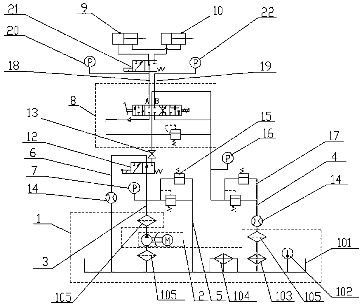
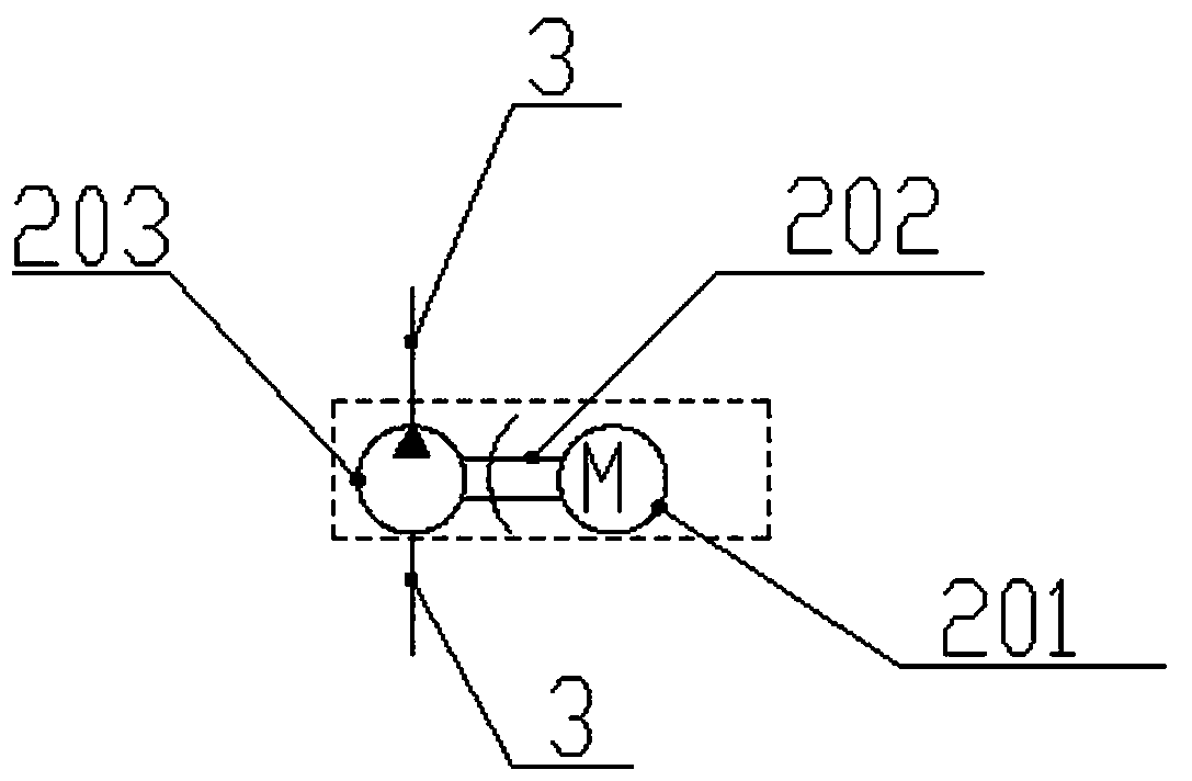
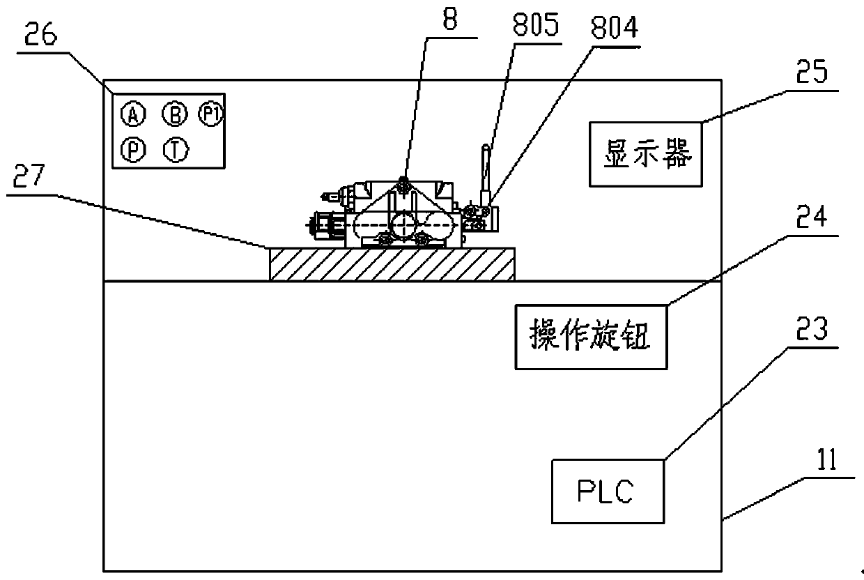
[0031] As shown in the figure, a tractor hydraulic multi-way valve test device includes a fuel tank assembly 1, a power assembly 2, a PLC control assembly, a multi-way valve to be tested 8, a simulated load cylinder 9, a lifter 10 and a box-type base 11. , the multi-way valve 8 to be tested and the PLC control assembly are all arranged on the box-type base 11, the fuel tank assembly 1 and the box-type base 11 are installed on the ground; the power assembly 2 is installed on the fuel tank assembly 1; The three-way solenoid valve I12 and the two-position three-way solenoid valve II21 are respectively connected between the power assembly 2 and the multi-way valve 8 to be tested, and between the multi-way valve 8 to be tested and the simulated load cylinder 9 and the lifter 10; the thermometer 102 is installed In the hydraulic oil tank 101; the flow meter 14 is installed ...


PUM


Abstract

The invention relates to a test device for a hydraulic multi-way valve of a tractor. The test device comprises an oil tank assembly, a power assembly, a PLC control assembly, a to-be-tested multi-wayvalve, an artificial load oil cylinder, a lifter and a box type base. The test device for the hydraulic multi-way valve of the tractor can test performance of the hydraulic multi-way valve under conditions of different flows, different temperatures and different system pressures, thereby providing technical and parameter guidance to control a process course of batched manufacturing of the hydraulic multi-way valves and guarding an outgoing quality pass.

Description

technical field [0001] The invention relates to the technical field of multi-way valve testing, in particular to a test device and a test method for a hydraulic multi-way valve of a tractor. Background technique [0002] Multi-way valve is a high-precision hydraulic component, which is an indispensable component for tractor with hydraulic output configuration. In recent years, the horizontal high-pressure and vertical high-pressure configuration developed by tractor relies on multi-way valve, which gradually replaces the traditional belt distribution. lifter structure. [0003] The most common faults of the multi-way valve components in the three-guarantee service in the market are internal leakage, external leakage, and stuck valve. The main reasons are concentrated in the control of the manufacturing process: 1. The matching gap between the valve stem and the valve body is large. Long-term use or unclean oil accelerates the wear of the valve stem and the valve body, destr...

Claims


Application Information

Patent Timeline
IPC IPC(8): F15B19/00F15B21/02
CPCF15B19/00F15B21/02
Inventor 王晓伟杜晓晓胡伟加志东杨文欣欧阳永吴健张凯周钰甘霖王南旗
Owner FIRST TRACTOR
Learn More