

Real-time bit synchronization correction method for quantum key generation system
A technology for generating system and quantum keys, which is applied in the field of quantum communication, can solve problems such as the decrease of the detection count at the receiving end and the decrease of the security key generation rate, so as to improve efficiency, increase the rate of security key generation, and increase the effective working time Effect
- Summary
- Abstract
- Description
- Claims
- Application Information
AI Technical Summary
Problems solved by technology
Method used
Image

Examples
Embodiment 1
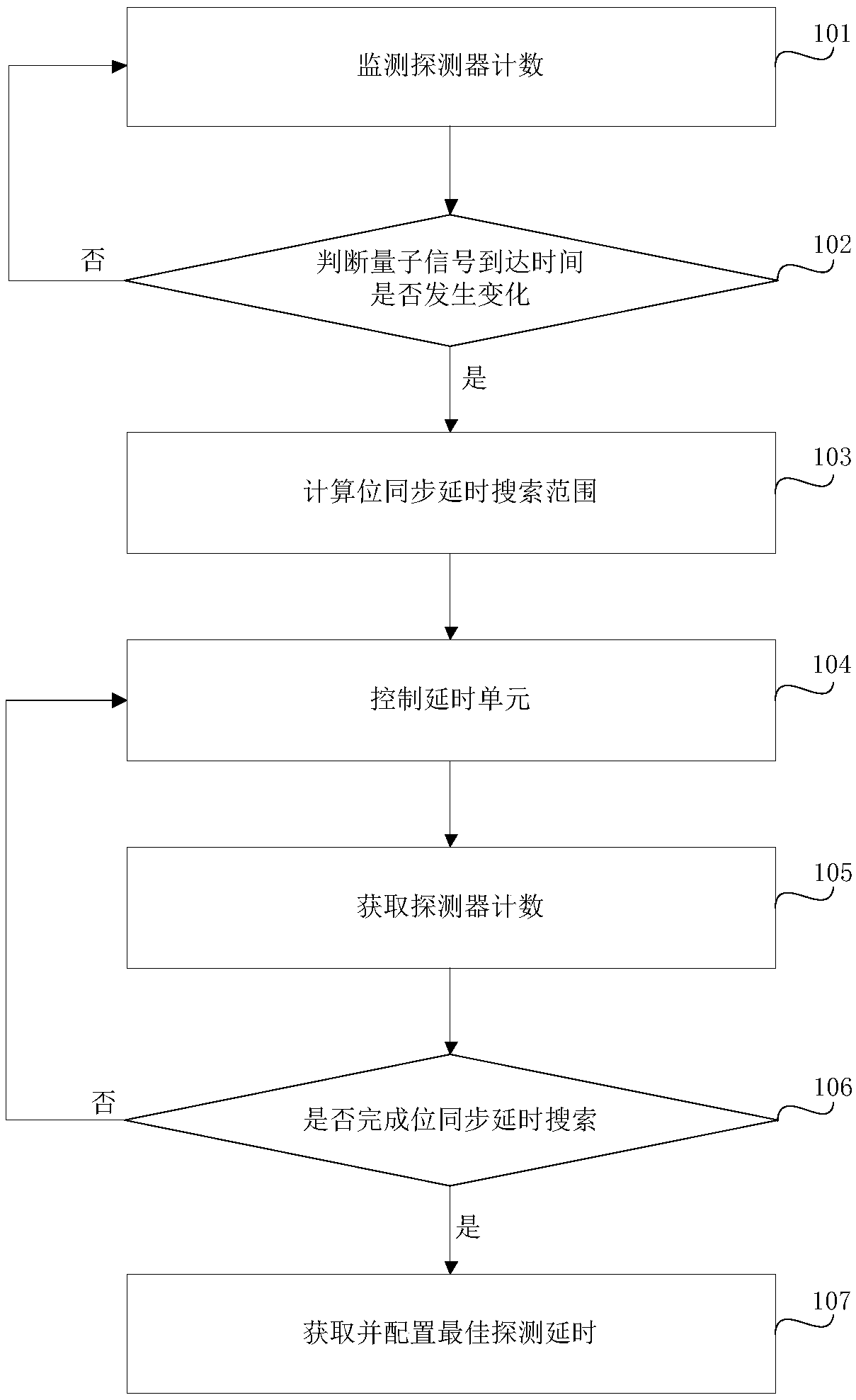
[0078] Step 101, the bit synchronization processing unit continuously reads the real-time count value of the detector and the corresponding real-time delay value of the detector, and obtains the relationship between the delay efficiency of the detector, the maximum count value of the detector per unit time and its corresponding optimal delay value. time value.
[0079] Detector count accumulation time T i The count value current_det_cnt of the detector unit time according to the current unit time i OK, the specific method is as follows:
[0080] When current_det_cnt i less than N i,1 pcs / s, detector counting effective accumulation time S i set to S i,1 ;
[0081] current_det_cnt i greater than N i,2 pcs / s, detector counting effective cumulative time T i set to S i,2 ;
[0082] current_det_cnt i not less than N i,1 pieces / second, and current_det_cnt i not greater than N i,2 pcs / s, detector counting effective accumulation time S i Set as;
[0083]
[0084] ab...
Embodiment 2
[0121] Step 201 is the same as step 101
[0122] Step 202 is the same as step 102
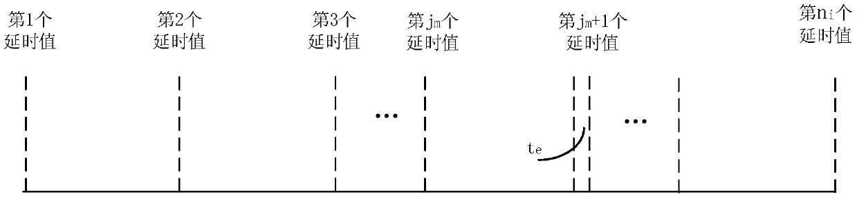
[0123] Step 203, the bit synchronization unit calculates the bit synchronization delay search range of each detector and the required search delay value.
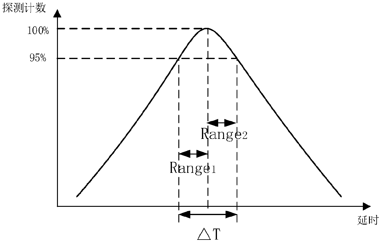
[0124] The bit synchronization delay search range of the i-th detector Range i It is set according to the detector response characteristic. Usually, the relationship between the detection efficiency of a certain detector and its detection time is as follows: figure 2 As shown, where the vertical axis data has been normalized to the maximum count det_cnt of the detector max , then the bit synchronization delay search range Rangei of the i-th detector is calculated as follows:
[0125] Range i =ΔT i ×γi
[0126] In the formula, ΔT i for figure 2 The delay difference between the two delay values corresponding to the lowest threshold set by the i-th detector, γ i It is a certain numerical value set artificially.
[0127] Under nor...
Embodiment 3
[0141] Step 301 is the same as step 101.
[0142] Step 302 is the same as step 102.
[0143] Step 303, calculating the bit synchronization delay search range of each detector and the required search delay value.
[0144] The bit synchronization delay search range of the i-th detector Range i It is set according to the detector response characteristic. Usually, the relationship between the detection efficiency of a certain detector and its detection time is as follows: figure 2 As shown, where the vertical axis data has been normalized to the maximum count det_cnt of the detector max , then the bit synchronization delay search range Range of the i-th detector i is calculated as follows:
[0145] Range i =ΔT i ×γ i
[0146] In the formula, ΔT i for figure 2 The delay difference between the two delay values corresponding to the lowest threshold set by the i-th detector, γ i It is a certain numerical value set artificially.
[0147] Under normal circumstances, the...
PUM
 Abstract
Description
Claims
Application Information