
Reverse double-turbine high-pressure axial flow pump

A twin-turbine, high-pressure shaft technology, applied to axial flow pumps, parts of pumping devices for elastic fluids, pumps, etc., can solve the problems of reducing water pump efficiency, increasing water flow resistance, and pressure loss, etc., to achieve reduction Small resistance, avoid pressure loss, increase the effect of pressure

Inactive Publication Date: 2020-08-11
GAOYOU HUAN LIU PUMP IND CO LTD
View PDF0 Cites 1 Cited by
  • Summary
  • Abstract
  • Description
  • Claims
  • Application Information

AI Technical Summary

Problems solved by technology

[0002] Axial flow pump is a common type of water pump at present. Due to the strong conveying capacity of the axial flow pump, the fluid is led to the outlet by the lift of the blades. It is axially in and axially out, and has the advantages of large flow. Forming an integrated body, there is no need for labor-intensive and time-consuming assembly processes of the motor, transmission mechanism, and water pump axis alignment at the installation site. The on-site installation is convenient and fast. Outside the pipe, however, this kind of playing pipe will increase the resistance of the water flow and slow down the speed of the water flow, and the gap between the turbofan and the inner wall of the pipe is large, which will easily cause pressure loss, thereby reducing the efficiency of the water pump

Method used


Image

  • Reverse double-turbine high-pressure axial flow pump
  • Reverse double-turbine high-pressure axial flow pump

Examples


Embodiment Construction

[0016] The following will clearly and completely describe the technical solutions in the embodiments of the present invention with reference to the accompanying drawings in the embodiments of the present invention. Obviously, the described embodiments are only some, not all, embodiments of the present invention. Based on the embodiments of the present invention, all other embodiments obtained by persons of ordinary skill in the art without making creative efforts belong to the protection scope of the present invention.

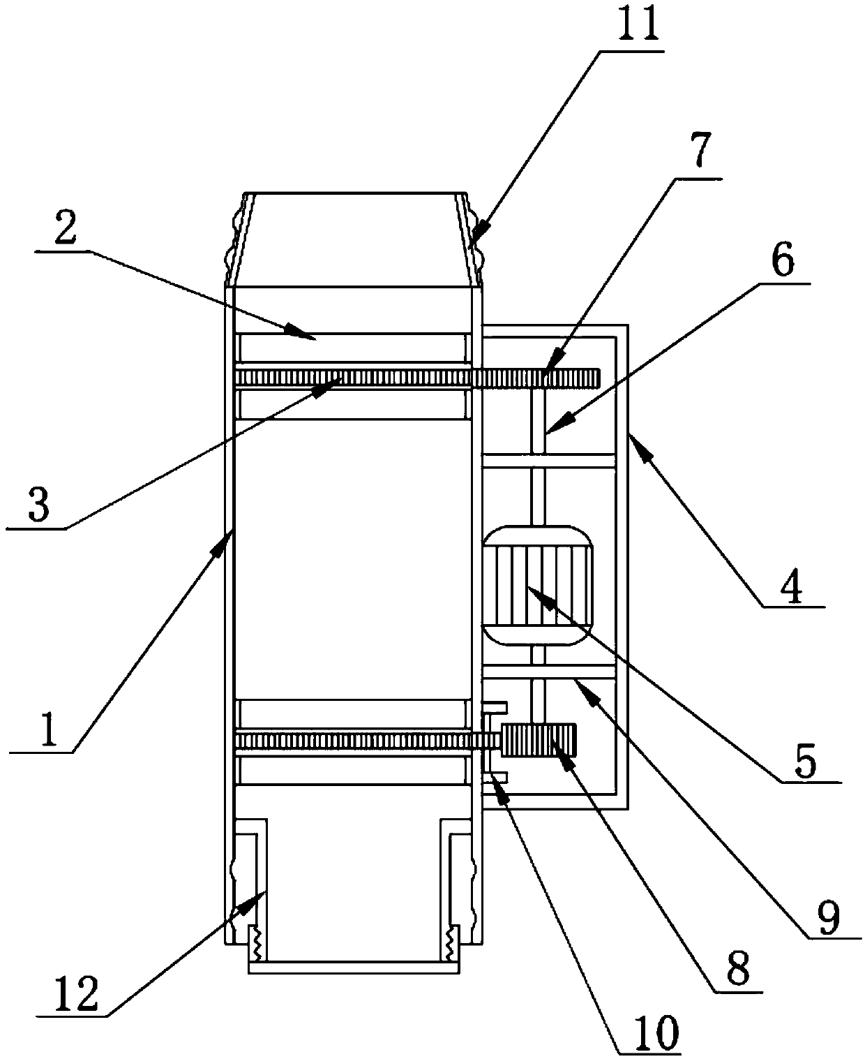
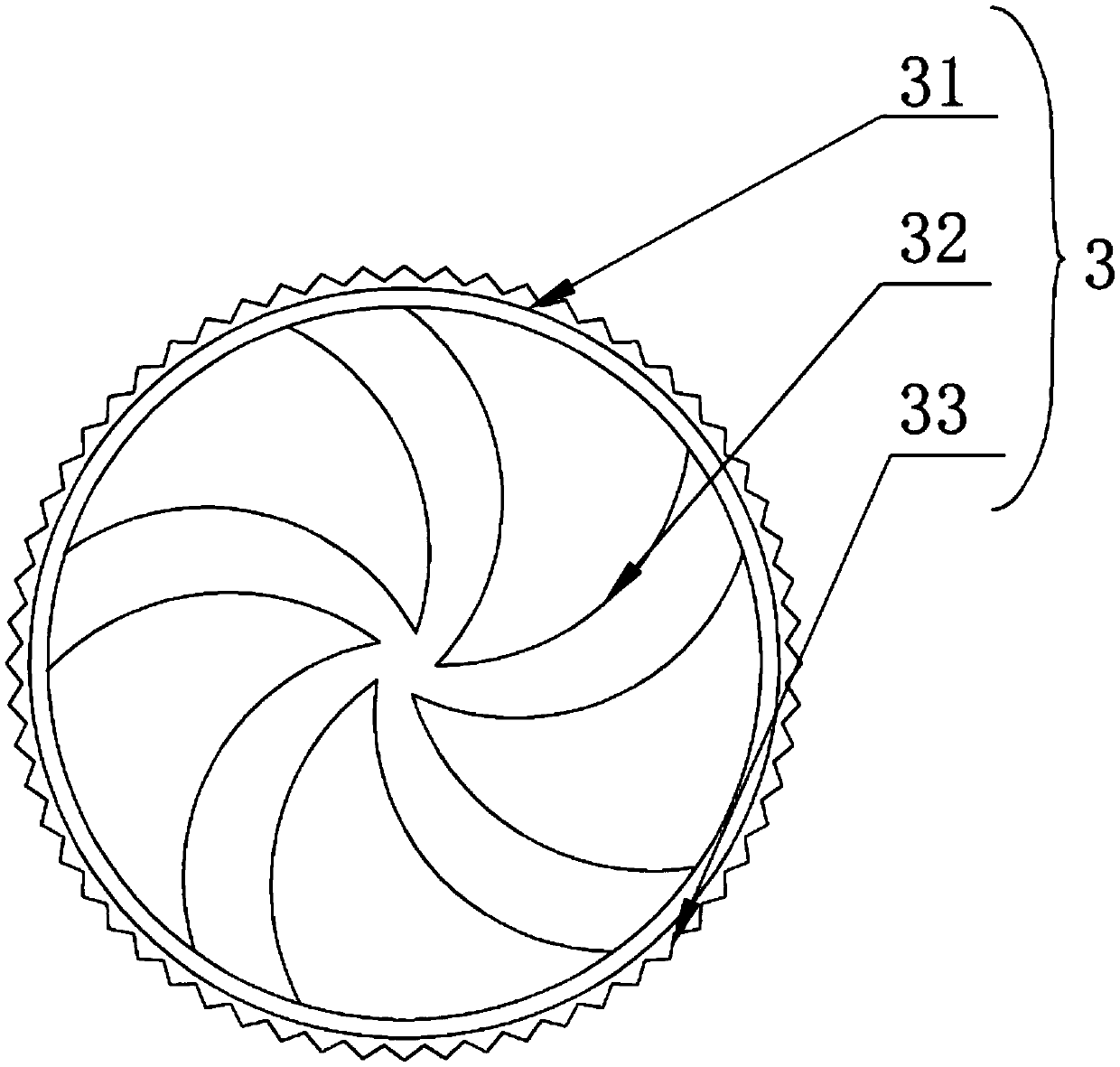
[0017] see Figure 1-2 , the present invention provides a technical solution: a reverse twin-turbine high-pressure axial flow pump, including a water delivery pipe 1, and two rotating bearings 2 with the same structure are arranged at the upper and lower parts of the inner cavity of the water delivery pipe 1, To facilitate the rotation of the turbofan 3, the inner walls of every two rotating bearings 2 are provided with a turbofan 3, the rotation of the turbof...


PUM


Abstract

The invention discloses a reverse double-turbine high-pressure axial flow pump, and relates to the technical field of axial flow pumps. The reverse double-turbine high-pressure axial flow pump comprises a water conveying pipe, two rotary bearings with same structures are arranged at the positions, close to the upper position and the lower position, of an inner cavity of the water conveying pipe, and turbofans are arranged on the inner walls of every two rotary bearings. A sealing shell is arranged on the right side of the water conveying pipe, a motor is arranged on the right side of the waterconveying pipe, a rotary shaft is arranged in an inner cavity of the motor, the rotary shaft penetrates through the surface of the motor, an upper gear is arranged at the bottom of the rotary shaft,a lower gear is arranged at the bottom of the rotary shaft, and the surface of the upper gear is clamped with the surface of the turbofan at the upper end. Two installation blocks with same structuresare arranged on the right side of the water conveying pipe, a rotating shaft is arranged between the two installation blocks with the same structures, a transmission gear is arranged on the surface of the rotating shaft, and the left side of the transmission gear is clamped with surface of the turbofan at the lower end. According to the reverse double-turbine high-pressure axial flow pump, the resistance of the flow is reduced, no gap exists between the turbofans and the inner wall of the water conveying pipe, the loss of pressure is avoided, and the efficiency of a water pump is improved.

Description

technical field [0001] The invention relates to the technical field of axial flow pumps, in particular to a reverse twin-turbine high-pressure axial flow pump. Background technique [0002] Axial flow pump is a common type of water pump at present. Due to the strong conveying capacity of the axial flow pump, the fluid is led to the outlet by the lift of the blades. It is axially in and axially out, and has the advantages of large flow. Forming an integrated body, there is no need for labor-intensive and time-consuming assembly processes of the motor, transmission mechanism, and water pump axis alignment at the installation site. The on-site installation is convenient and fast. Outside the pipe, however, this kind of playing pipe will increase the resistance of the water flow and slow down the speed of the water flow, and the gap between the turbofan and the inner wall of the pipe is large, which is easy to cause pressure loss, thereby reducing the efficiency of the water pum...

Claims


Application Information

Patent Timeline
IPC IPC(8): F04D3/00F04D13/06F04D29/18F04D29/20F04D29/52
CPCF04D3/00F04D13/06F04D29/185F04D29/20F04D29/528
Inventor 赵玉明赵昶
Owner GAOYOU HUAN LIU PUMP IND CO LTD
Learn More