Intelligent speed reducer

A reducer and intelligent technology, applied in mechanical equipment, measuring devices, instruments, etc., can solve the problems of increased inspection difficulty, delayed production process, and the inability of the reducer to detect working conditions, so as to reduce maintenance downtime and improve production. The effect of efficiency

Pending Publication Date: 2020-08-11
ZHEJIANG UNIV KUNSHAN INNOVATION INST
View PDF21 Cites 2 Cited by
  • Summary
  • Abstract
  • Description
  • Claims
  • Application Information

AI Technical Summary

Problems solved by technology

The existing reducer cannot detect its working condition during operation. Whether the reducer is abnormal can only be checked by inspection. For some occasions where radiation is not conducive to inspe

Method used


Image

  • Intelligent speed reducer

Examples


Embodiment Construction

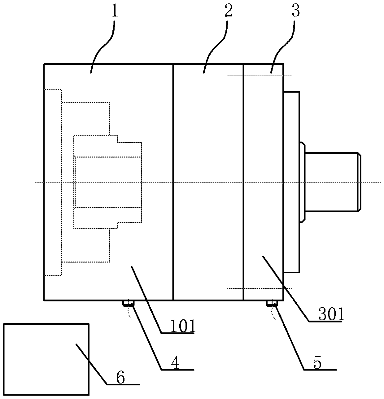
[0016] An intelligent reducer, see figure 1 : It includes an input end assembly 1, an intermediate transmission part 2, and an output end assembly 3. The input end assembly 1 is provided with a first sensor group corresponding to the connection position of each component, and the first sensor group receives corresponding parameters of vibration, torque, and force The output end assembly 3 is provided with a second sensor group corresponding to the connection position of each component, and the first sensor group receives the corresponding parameters of vibration, torque, and force; the input end assembly 1 and the output end assembly 3 are all provided with a grating, and the grating It is used to analyze the angle difference between the input and output rotation of the reducer, and to detect transmission errors and differential stability; the outer casing 101 of the input end assembly 1 is also provided with a first signal receiver 4, the first signal receiver 4 It is used to...


PUM


Abstract

The invention provides an intelligent speed reducer. On the basis of a traditional speed reducer, modern intelligent control means such as the latest sensor technology and the communication and information technology are comprehensively applied, and the running state of the speed reducer is monitored in real time. An input end assembly is provided with a first sensor group corresponding to the connection position of each component, and the first sensor group receives corresponding parameters of vibration, torque and force; an output end assembly is provided with a second sensor group corresponding to the connection position of each component, and the first sensor group receives corresponding parameters of vibration, torque and force; gratings are arranged in the input end assembly and theoutput end assembly, and the gratings are used for analyzing the angle difference between the input rotation and the output rotation of the speed reducer and detecting transmission errors and differential stability; and a first signal receiver is further arranged on an outer shell of the input end assembly, and a second signal receiver is further arranged on an outer shell of the output end assembly.

Description

technical field [0001] The invention relates to the technical field of reducer structure, in particular to an intelligent reducer. Background technique [0002] The reducer is a relatively precise machine, an independent transmission component used to reduce the speed, transmit power, and increase torque, and is widely used in modern machinery. The existing reducer cannot detect its working condition during operation. Whether the reducer is abnormal can only be checked by inspection. For some occasions where radiation is not conducive to inspection, the inspection is more difficult; so now Some reducers cannot predict possible faults in advance, and can only be discovered when they are damaged, which delays the subsequent production process. Contents of the invention [0003] In view of the above problems, the present invention provides an intelligent reducer, which, on the basis of the traditional reducer, monitors the operating status of the reducer in real time through...

Claims


Application Information

Patent Timeline
IPC IPC(8): F16H57/01F16H57/02G01D21/02
CPCF16H57/01F16H57/02G01D21/02F16H2057/012F16H2057/018F16H2057/02026
Inventor 胡群飞张慧明陈鹏吴俊峰
Owner ZHEJIANG UNIV KUNSHAN INNOVATION INST
Why Eureka
Try Eureka