Multi-flow evaporative condenser

An evaporative condenser and multi-process technology, applied in steam/steam condensers, water shower coolers, direct contact heat exchangers, etc., can solve the problems of reduced heat transfer rate, reduced heat transfer efficiency, and high maintenance costs , to achieve the effect of reducing evaporation heat and reducing resistance

Active Publication Date: 2020-08-11
SHANDONG JIANZHU UNIV
View PDF9 Cites 6 Cited by
  • Summary
  • Abstract
  • Description
  • Claims
  • Application Information

AI Technical Summary

Problems solved by technology

[0004] The Chinese patents of CN108562071A, CN108253667A and CN1967096A disclose a coil evaporative condenser. In order to reduce the formation of dry wall and scaling on the surface of the heat exchange tube, the structure and process of the coil evaporative condenser are optimized, but the Due to the limitation of the layout of the coil, there are the following problems: limited by the radius of the elbow and the arrangement of the tube bundle, the tube spacing is too large, and "flying water" and dry wall are prone to occur, resulting in scaling on the outer wall of the tube; the tube bundle layout is not compact , the heat transfer area per unit volume is too small; due to the large pipe length and many elbows of the coil, the flow resistance of the fluid in the pipe is relatively large, and the heat transfer efficiency is low, especially for the condensation phase change process in the pipe, because the vapor and liquid in the pipe cannot Timely separation, condensate continues to accumulate, and the condensation heat transfer process in the tube deteriorates sharply; when the coil leaks due t...

Method used


Image

  • Multi-flow evaporative condenser
  • Multi-flow evaporative condenser

Examples


Embodiment Construction

[0024] The technical solutions in the embodiments of the present invention will be clearly and completely described below in conjunction with the accompanying drawings in the embodiments of the present invention. Obviously, the described embodiments are only some, not all, embodiments of the present invention.

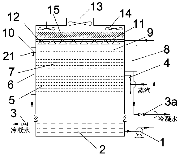
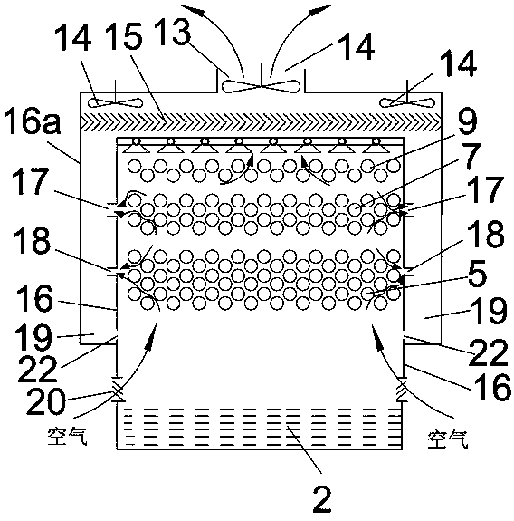
[0025] figure 1 and figure 2A multi-flow evaporative condenser is shown, including cooling water circulation components, heat exchange components and air induction components. The cooling water circulation component includes a circulating water pump 1, a circulating water pool 2, a main spraying water pipe 11, and a nozzle 12. The cooling water in the circulating water pool 2 is connected to the inlet of the circulating water pump 1 through a pipeline, and the outlet of the circulating water pump 1 is connected to the main spraying water pipe 11 through a pipeline. Several nozzles 12 are connected at equal intervals on the shower main water pipe 11 .

[0026] The he...


PUM


Abstract

The invention discloses a multi-flow evaporative condenser, and belongs to the technical field of condensing equipment. A wet air outlet is added according to the increase of air humidity, so that nearly-saturated wet air can be directly blown away by a fan while rising in a shell; the resistance encountered during upward flowing of the wet air can be reduced compared with the original way that the wet air continually rises across a heat exchange tube bundle; and the pump power consumption of the fan is reduced. In addition, more dry air can be enabled to enter the shell in order to improve the mass and heat transfer efficiency between the air and cooling water. In the condenser, a horizontal tube bundle is adopted instead of a traditional coil in order to realize arrangement of the tube spacing according to the principle of optimal thicknesses of liquid films outside tubes, ensure the formation of thin and uniform liquid films outside the tubes, improve the evaporative heat transfer rate, avoid the occurrence of scaling, and improve the compactness of a heat exchanger so as to reduce the size of equipment. In the multi-flow evaporative condenser, multiple flows are adopted insteadof the traditional single flow, so that timely separation of condensate in the tubes is facilitated so as to strengthen condensation heat transfer in the tubes.

Description

technical field [0001] The invention relates to a multi-flow evaporative condenser, which belongs to the technical field of condensation equipment. [0002] technical background [0003] The evaporative condenser is a high-efficiency condensation heat exchange device that uses water evaporation to absorb latent heat and then cool the medium. Compared with the traditional water-cooled condenser, the evaporative condenser is equivalent to integrating the condenser and the cooling tower, which saves the power consumption of the circulating water pump and reduces equipment investment; the vaporized phase change heat transfer of water replaces the sensible heat transfer of water heat, reducing water loss; using the wet bulb temperature of the air to reduce the condensation temperature of circulating water and improve heat transfer efficiency. Therefore, the evaporative condenser with the characteristics of water saving, energy saving and investment saving is gradually used in pow...

Claims


Application Information

Patent Timeline
IPC IPC(8): F28B1/02F28B9/04F28B9/08F28D5/02F28F25/02
CPCF28B1/02F28B9/04F28B9/08F28D5/02F28F25/02
Inventor 杨洛鹏张林华曲云霞李安桂宫淑兰
Owner SHANDONG JIANZHU UNIV
Why Eureka
Try Eureka