
Airborne motor drive control system

A motor drive control and drive control technology, applied in the control system, motor control, motor speed or torque control, etc., can solve the problem of high procurement and replacement costs, large power margin of the controller, and power-to-weight ratio It can reduce the cost of procurement and use, improve the efficiency of on-site maintenance, and simplify the types and specifications.

Pending Publication Date: 2020-08-11
XIAN AIRCRAFT DESIGN INST OF AVIATION IND OF CHINA
View PDF7 Cites 1 Cited by
  • Summary
  • Abstract
  • Description
  • Claims
  • Application Information

AI Technical Summary

Problems solved by technology

Regarding the above technical solution, the inventors found that there are at least some technical problems as follows: For example, although the strategy of time-division multiplexing reduces the number of dedicated controllers and idle time, and improves the overall use efficiency of the controllers, the remaining power of the controllers Large quantity, heavy weight, high procurement and replacement costs; although the interchange method of LRM modules realizes the commonality of different load controllers, improves the reliability of the electromechanical system and the performance of rapid on-site maintenance, but there is also the weight of a single controller Large, low power-to-weight ratio, single control load, can only control motor loads with speed regulation, not compatible with position closed-loop control motor loads

Method used


Image

  • Airborne motor drive control system
  • Airborne motor drive control system

Examples


Embodiment Construction

[0025] Example embodiments will now be described more fully with reference to the accompanying drawings. Example embodiments may, however, be embodied in many forms and should not be construed as limited to the examples set forth herein; rather, these embodiments are provided so that this disclosure will be thorough and complete and will fully convey the concept of example embodiments to those skilled in the art. The described features, structures, or characteristics may be combined in any suitable manner in one or more embodiments.

[0026] Furthermore, the drawings are merely schematic illustrations of the present disclosure and are not necessarily drawn to scale. The same reference numerals in the drawings denote the same or similar parts, and thus repeated descriptions thereof will be omitted. Some of the block diagrams shown in the drawings are functional entities and do not necessarily correspond to physically or logically separate entities. These functional entities ...


PUM


Abstract

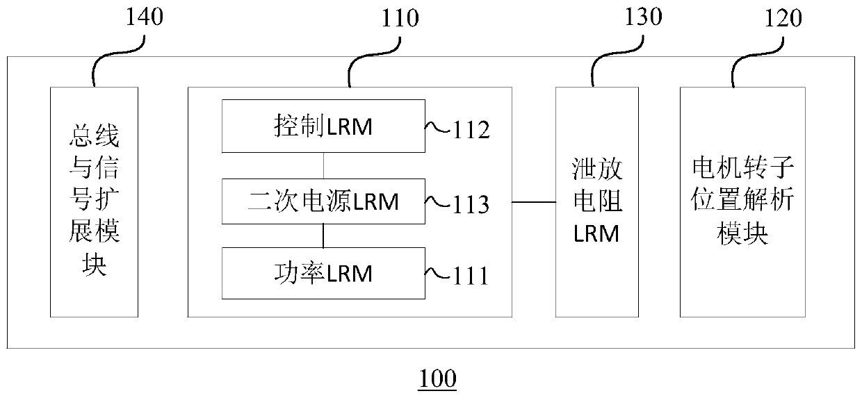
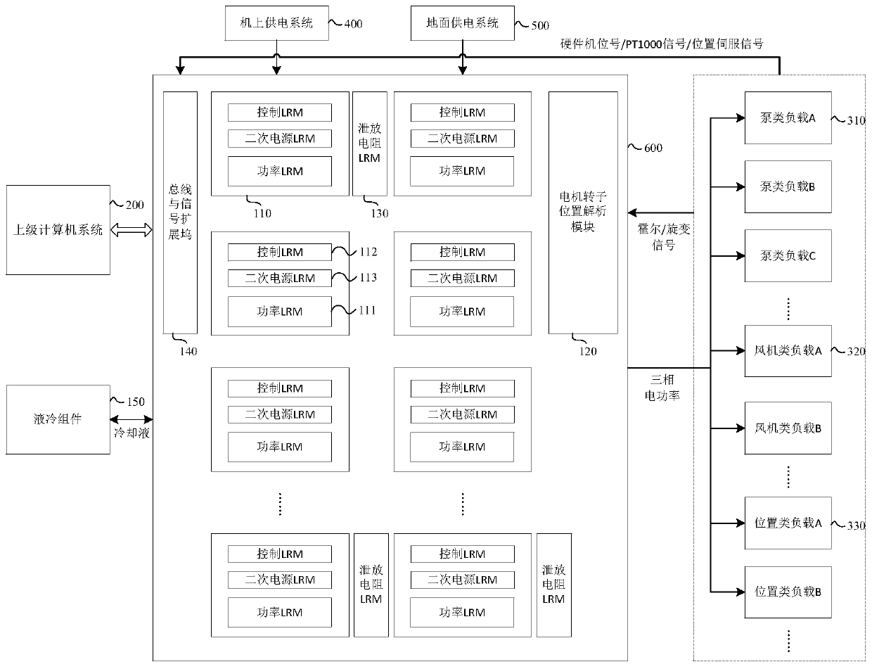
The embodiment of the invention relates to an airborne motor drive control system. The airborne motor drive control system comprises N drive control units and a motor rotor position analysis module, wherein the N drive control units are used for identifying a specific load and loading a control method; wherein N is an integer greater than or equal to 1. Each drive control unit comprises a power LRM, a control LRM and a secondary power supply LRM which are electrically connected with one another. The motor rotor position analysis modul is used for detecting a position signal of the load, the control LRM is used for controlling the operation state of the load, the power LRM is used for providing alternating current required by each phase of winding for the load, and the secondary power supply LRM is used for providing driving voltage for a drive control unit hardware board card of the load. According to the embodiment of the invention, universal and centralized control of various electromechanical loaders in a certain area of the fuselage of the aircraft is realized, the number, type and specification of airborne motor controllers are simplified, the purchase and use cost is reduced,and the field maintenance efficiency is improved.

Description

technical field [0001] Embodiments of the present disclosure relate to the technical field of aviation electrical equipment, and in particular to an airborne motor drive control system. Background technique [0002] With the wide application of the airborne 270V high-voltage DC power supply system, the number of motor controllers required for engine electric starting, electric environmental control, hydraulic electric pumps and high-lift systems on large passenger aircraft has increased significantly. Traditional airborne motor-specific controllers have many types, heavy weight, different power levels, and lack of versatility and compatibility, resulting in an increase in the number of spare parts and tools for disassembly and assembly, which is not conducive to on-site fault location and maintenance work. [0003] In related technologies, there is a general-purpose motor controller based on a time-division multiplexing strategy to drive loads such as environmental control a...

Claims


Application Information

Patent Timeline
IPC IPC(8): H02P5/00H02P5/60
CPCH02P5/00H02P5/60H02P2203/03
Inventor 方淳李巍巨亚鸽
Owner XIAN AIRCRAFT DESIGN INST OF AVIATION IND OF CHINA
Learn More