
Skull milling cutter for craniotomy

A surgical, cranial technology, applied in the field of medical devices, can solve the problems of increasing the risk of infection in patients with surgical costs, unfavorable positioning and drilling, and reducing surgical efficiency, so as to reduce scalp damage, increase drilling efficiency, and avoid stuck. damage effect

Inactive Publication Date: 2020-08-14
郭永强
View PDF0 Cites 5 Cited by
  • Summary
  • Abstract
  • Description
  • Claims
  • Application Information

AI Technical Summary

Problems solved by technology

[0005] In order to make up for the deficiencies of the existing technology, the diameter of the drill rod used by the skull milling cutter in the prior art is large, which is not conducive to rapid positioning and drilling. After drilling with a smaller diameter drill rod, it is necessary to ream the hole, which increases the number of operations. Time, reduce operation efficiency, increase operation cost and the risk of patient infection, a kind of craniotomy craniotomy that the present invention proposes

Method used


Image

  • Skull milling cutter for craniotomy
  • Skull milling cutter for craniotomy
  • Skull milling cutter for craniotomy

Examples


Embodiment approach

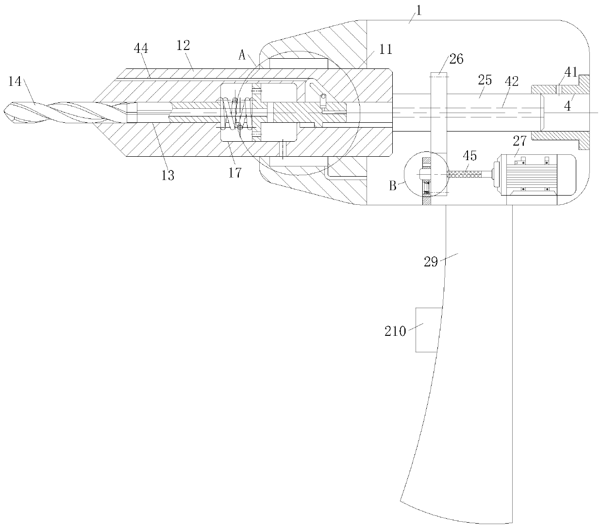
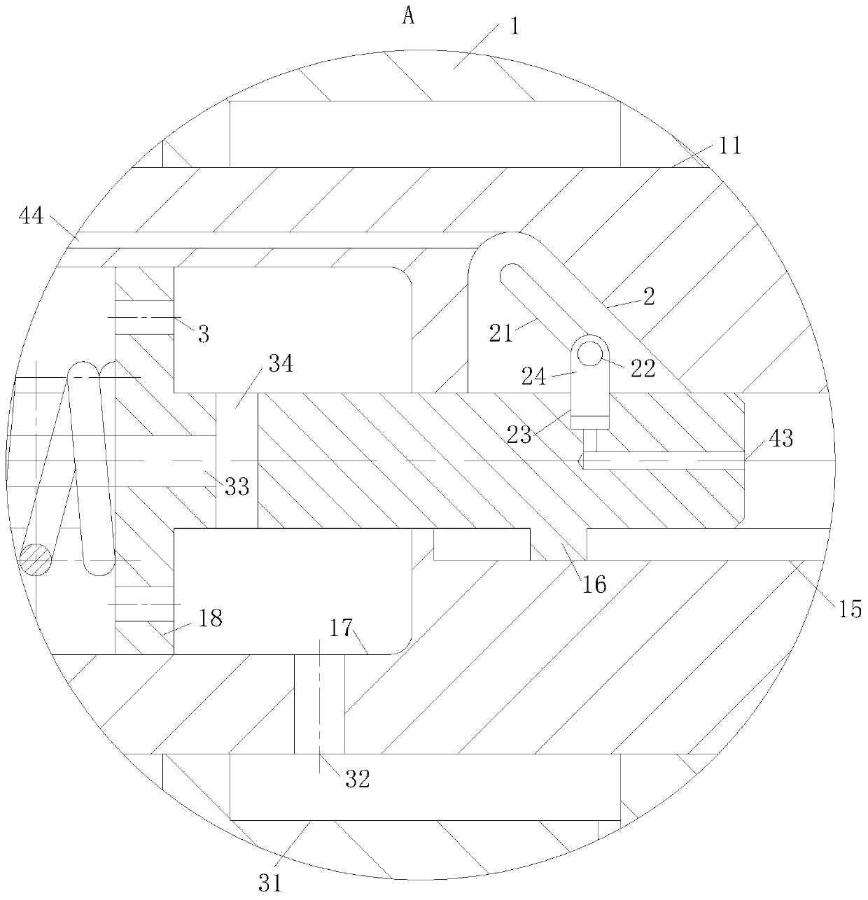
[0023] As an embodiment of the present invention, an annular groove 31 is provided on the inner wall of the No. 1 sliding hole 11 corresponding to the sliding cavity 17, and the annular groove 31 communicates with a water tank through a pipeline and a water pump, and physiological saline is housed in the water tank; The No. 1 drill pipe 12 is provided with a water hole 32 connecting the sliding chamber 17 and the ring groove 31; the No. 2 drill pipe 14 is provided with a No. 2 hole 33 along the axial direction. The drill bit is connected, and the other end is communicated with the sliding cavity 17 through the third hole 34. By filling the sliding cavity 17 with physiological saline, it is then sprayed out through the second hole 33 to speed up the efficiency of chip removal when the skull is drilled; The normal saline with pressure is pumped into the tank 31, and the normal saline is filled into the slide chamber 17 through the water hole 32, and then it is sprayed out from th...


PUM


Abstract

The invention belongs to the technical field of medical instruments, and particularly relates to a skull milling cutter for craniotomy. The skull milling cutter comprises a shell; a first sliding holeis formed in the shell, a first drill rod is rotationally connected into the first sliding hole, and a second drill rod is slidably connected into a first hole formed in the first drill rod; a firstsliding groove is formed in the first hole, a sliding block is slidably connected into the first sliding groove, and the sliding block is fixedly connected with the first drill rod; a sliding cavity is formed in the first hole, a limiting ring is fixedly connected to the position, corresponding to the sliding cavity, of the first drill rod, and the second drill rod on the side, away from the sliding block, of the limiting ring is sleeved with a reset spring; a groove is formed in the position, corresponding to the sliding block, in the first hole, an obliquely-arranged second sliding groove isformed in the groove, and a rotating pin is connected into the second sliding groove in a sliding mode; and a second sliding hole is formed in the position, corresponding to the second sliding groove, of the second drill rod, a sliding column is slidably connected into the second sliding hole, and the end, close to the rotating pin, of the sliding column is fixedly connected with the rotating pin. Accurate positioning is achieved through the second drill rod, and the drilling accuracy of the skull milling cutter is guaranteed.

Description

technical field [0001] The invention belongs to the technical field of medical instruments, in particular to a skull milling cutter for craniotomy. Background technique [0002] Craniotomy, also known as craniotomy, is a type of cranial surgery, which refers to the use of mechanical equipment to open the patient's skull to perform some unconventional treatments. [0003] The procedure of opening the patient's skull is usually to locate the positioning holes at three points in the area, and then use a milling cutter to cut between the positioning holes to remove the skull. This process often uses a skull milling cutter and a drilling drill. Both the knife and the drill are craniotomy instruments commonly used in neurosurgery. During brain surgery, the high-speed rotating milling unit is used to cut open the skull. When positioning the three holes, it is necessary to cut a hole in the skull. The existing operation method directly uses trephine drilling. However, when the trep...

Claims


Application Information

Patent Timeline
Patent Type & Authority Applications(China)
IPC IPC(8): A61B17/16A61B90/00
CPCA61B17/1659A61B17/1695A61B90/08A61B2017/564A61B2090/08021A61B2217/007
Inventor 郭永强李志城
Owner 郭永强
Learn More