
Spinal operation bracket device for neurosurgery

A neurosurgery and bracket device technology, which is applied in the fields of surgery, operating table, medical science, etc., can solve the problems of reducing the efficiency of adjusting the distance between the front and rear of the head support, the outer skin cover is damaged and bursting, and the patient cannot be flexibly adjusted, and achieves improved convenience. performance, improve regulation efficiency, and avoid the effect of contaminant adhesion

Inactive Publication Date: 2020-08-14
胡增永
View PDF1 Cites 2 Cited by
  • Summary
  • Abstract
  • Description
  • Claims
  • Application Information

AI Technical Summary

Problems solved by technology

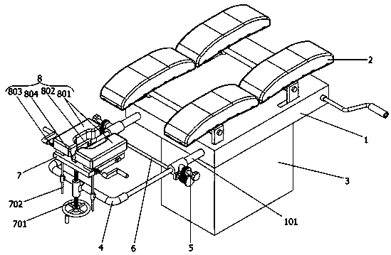
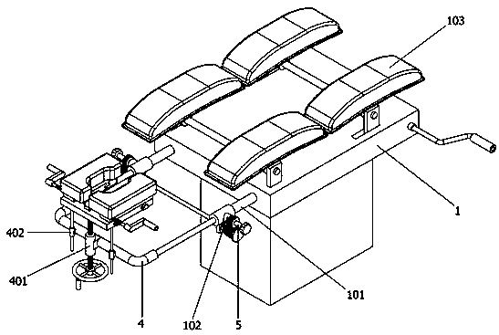
[0005] In order to solve the above-mentioned technical problems, the present invention provides a spinal surgery bracket device for neurosurgery to solve the following deficiencies in the actual use of the existing spinal surgery bracket device, such as: 1. The arc-shaped sponge support plate on the bracket device lacks an effective protective structure outside, so that after a long-term use of the arc-shaped sponge support plate, it is very easy to cause damage to the outer leather cover, and after long-term use, A large amount of pollutants will be attached to the surface of the arc-shaped sponge strut, which makes it extremely inconvenient for cleaning personnel to clean the arc-shaped sponge strut; However, when adjusting, it is necessary to loosen the two fastening handwheels in turn and then adjust them. After the adjustment, both handwheels must be tightened in turn, which reduces the adjustment efficiency of the distance between the front and rear of the headrest; 3. The headrest on the existing spinal surgery bracket device is integrally formed, so it cannot be flexibly adjusted according to patients with different head sizes

Method used


Image

  • Spinal operation bracket device for neurosurgery
  • Spinal operation bracket device for neurosurgery
  • Spinal operation bracket device for neurosurgery

Examples


Embodiment Construction

[0030] Embodiments of the present invention will be further described in detail below in conjunction with the accompanying drawings and examples. The following examples are used to illustrate the present invention, but should not be used to limit the scope of the present invention.

[0031] as attached figure 1 To attach Figure 10 Shown:

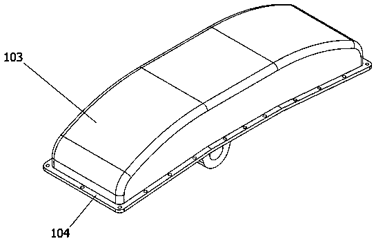
[0032] The present invention provides a spinal surgery bracket device for neurosurgery, comprising: a bracket body 1, which is fixedly connected to the upper end surface of a support table 3, and the bracket body 1 also includes a support slide 101, a threaded thickening block 102. The arc-shaped sponge support plate 103 and the connecting bottom plate 104, the front end of the bracket main body 1 is symmetrically arranged with two support slides 101, and each support slide 101 is provided with a Connected thread thickening block 102, two support slides 101 front side bottoms are welded with a square mounting block, bracket main body 1 u...


PUM


Abstract

The invention provides a spinal operation bracket device for neurosurgery. The device comprises a bracket main body, wherein the bracket main body is fixedly connected to the upper end surface of a support table, and four protection mechanisms are mounted at the upper part of the bracket main body. Through cooperation of fastening mechanisms and a transmission mechanism, when the front-back distance of a head supporting mechanism needs to be adjusted, by rotating the fastening mechanism on the right side anticlockwise, a first gear on the right side drives a second gear on the right side to rotate clockwise, and then a first gear on the left side is driven by a second gear on the left side to rotate anticlockwise at the same time; due to the fact that internal threads of two thread thickening blocks are reverse threads, the two fastening mechanisms synchronously move in the opposite directions, so that a slide supporting mechanism is failed to fix, then the distance of the head supporting mechanism is adjusted by adjusting the front-back distance of the slide supporting mechanism, then fixing can be completed by clockwise rotating one of the fastening mechanisms, and thus the efficiency of adjusting the front-back distance of the head supporting mechanism is improved.

Description

technical field [0001] The invention belongs to the technical field of spinal surgery brackets, and more specifically relates to a spinal surgery bracket device for neurosurgery. Background technique [0002] Neurosurgery is a branch of surgery, which uses unique neurosurgery research methods to study the human nervous system, such as the brain, spinal cord and peripheral nervous system, as well as related diseases, based on surgery as the main treatment method. Subsidiary organs, such as skull, scalp, cerebrovascular meninges and other structural injuries, inflammation, tumors, deformities and certain genetic metabolic disorders or dysfunctional diseases, such as: the etiology and pathogenesis of epilepsy, Parkinson's disease, neuralgia and other diseases , and explore new diagnostic, therapeutic, and preventive technologies as a high-level, precise, and cutting-edge discipline. [0003] For example, application number: CN201910049301.6 The present invention discloses a sp...

Claims


Application Information

Patent Timeline
Patent Type & Authority Applications(China)
IPC IPC(8): A61G13/00A61G13/12A61G13/08
CPCA61G13/00A61G13/08A61G13/121A61G13/1225A61G13/1285A61G13/129
Inventor 胡增永
Owner 胡增永
Learn More