
A Construction Method for Longitudinal Buried Drainage of Asphalt Layer of Highway Bridge

A construction method and technology of highway bridges, applied in bridges, bridge materials, bridge construction, etc., can solve the problems of increased operation and maintenance costs of road products, uneven road surface friction, endangering driving safety, etc., achieve good social and economic benefits, and prolong the use Years, the effect of avoiding water damage

Active Publication Date: 2021-08-24
云南阳光道桥股份有限公司
View PDF8 Cites 0 Cited by
  • Summary
  • Abstract
  • Description
  • Claims
  • Application Information

AI Technical Summary

Problems solved by technology

Since the overall cast-in-place cement concrete bridge deck pavement cannot be made absolutely flat, there are small pits and unevenness, and the asphalt concrete pavement structure design has a certain void ratio, in rainy or wet conditions, the pits will be In addition, there is no drainage layer between the overall cast-in-place cement concrete bridge deck pavement and the asphalt concrete pavement layer. The water in the pits will remain for a long time, and the hydrodynamic pressure will be generated under the condition of high-speed wheels, causing the asphalt layer to break down. early damage
Or when the temperature rises in clear weather, the water in the pits often spreads to the road surface along the gaps in the asphalt concrete surface layer, causing the road surface to appear in uneven dry and wet states, and the road surface friction is uneven, endangering driving safety
Generally, there is no drainage and drying layer between asphalt concrete and cement concrete composite bridge decks, which is prone to water damage and early disease of bridge asphalt pavement, which leads to increased operation and maintenance costs of road products and reduces the life cycle time of roads.

Method used


Image

  • A Construction Method for Longitudinal Buried Drainage of Asphalt Layer of Highway Bridge

Examples


Embodiment Construction

[0037] The technical solutions in the embodiments of the present invention will be clearly and completely described below in conjunction with the embodiments of the present invention. Apparently, the described embodiments are only some of the embodiments of the present invention, not all of them. Based on the embodiments of the present invention, all other embodiments obtained by persons of ordinary skill in the art without making creative efforts belong to the protection scope of the present invention.

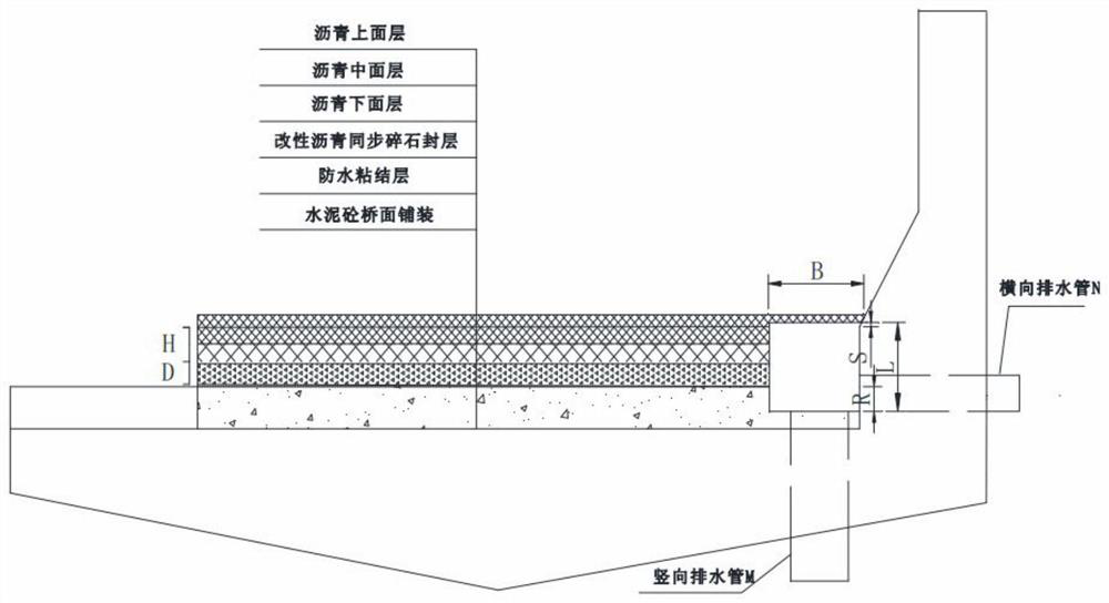
[0038] A construction method for vertically buried drainage of asphalt layers of highway bridges, comprising the following sequential steps:

[0039] Step 1: Bridge cement concrete bridge deck pavement:

[0040] The T-beam of the bridge is installed in place, after pouring the cement concrete of the transverse diaphragm and the horizontal connection of the wing plate to the cement concrete, making and installing the cement concrete bridge deck pavement steel mesh and fixing i...


PUM

PropertyMeasurementUnit
particle diameteraaaaaaaaaa

Abstract

The invention discloses a construction method for vertically buried drainage of asphalt layers of highway bridges, comprising the following steps: cement concrete bridge deck pavement, cement concrete bridge deck pavement rough milling, waterproof adhesive layer construction, modified asphalt synchronous crushing Construction of stone seal layer, construction of asphalt concrete lower layer of bridge deck, longitudinal cutting of lower layer along transverse slope or curve low-end anti-collision wall or inner edge of guardrail seat and installation of hollow drainage pipes, adhesive layer sprinkling, construction of bridge deck asphalt upper layer . The invention solves the problem of drainage between asphalt concrete and cement concrete composite bridge decks, improves the water damage resistance of the asphalt pavement of highway bridges, effectively prevents early water damage diseases of the asphalt pavement of highway bridges, improves the use effect of the asphalt pavement of highway bridges and prolongs the service life .

Description

technical field [0001] The invention relates to the technical field of highway construction, in particular to a construction method for vertically buried drainage of asphalt layers of highway bridges. Background technique [0002] Asphalt concrete and cement concrete composite bridge deck is a bridge deck pavement structure often used in highways and urban roads. or three-layer asphalt concrete pavement. Since the overall cast-in-place cement concrete bridge deck pavement cannot be made absolutely flat, there are small pits and unevenness, and the asphalt concrete pavement structure design has a certain void ratio, in rainy or wet conditions, the pits will be In addition, there is no drainage layer between the overall cast-in-place cement concrete bridge deck pavement and the asphalt concrete pavement layer. The water in the pits will remain for a long time, and the hydrodynamic pressure will be generated under the condition of high-speed wheels, causing the asphalt layer t...

Claims


Application Information

Patent Timeline
Patent Type & Authority Patents(China)
IPC IPC(8): E01D19/08E01D101/34E01D101/40E01D101/24
CPCE01D19/083E01D19/086E01D2101/24E01D2101/34E01D2101/40
Inventor 张林祥孔垂荣杨忠艳李烨荀家正李荣盛
Owner 云南阳光道桥股份有限公司
Learn More