
Electrostatic flash micro-spray circulation cooling system for high-power chip heat dissipation

A circulating cooling system and chip heat dissipation technology, applied in the direction of circuits, electrical components, electrical solid devices, etc., can solve the problems of miniaturization, integrated cooling system design and packaging, difficult precise cooling of semiconductor chips, explosive fragmentation of refrigerants, etc. problem, to avoid the sharp increase of the chip temperature, improve the cooling efficiency and uniformity, and achieve the effect of high atomization quality

Active Publication Date: 2020-10-02
常州江苏大学工程技术研究院
View PDF7 Cites 1 Cited by
  • Summary
  • Abstract
  • Description
  • Claims
  • Application Information

AI Technical Summary

Problems solved by technology

[0005] Refrigerant flash spray cooling ability is strong, which is expected to solve the heat dissipation problem of high-power chips. However, due to the flash evaporation, bubbles are often generated inside and on the surface of the refrigerant. The bursting of the bubbles leads to explosive fragmentation of the refrigerant. Spray cone angle (> 90º), it is difficult to implement precise cooling for high-power semiconductor chips with a heat dissipation area of ​​only tens of square millimeters, and a large amount of working fluid is deposited or splashed outside the heat dissipation surface, which easily leads to a decrease in cooling efficiency and energy waste
In addition, in order to obtain better atomization and cooling effects, the spray distance is often set to more than 30 mm, resulting in a bulky spray chamber, making it difficult to realize miniaturized and integrated cooling system design and packaging

Method used


Image

  • Electrostatic flash micro-spray circulation cooling system for high-power chip heat dissipation
  • Electrostatic flash micro-spray circulation cooling system for high-power chip heat dissipation
  • Electrostatic flash micro-spray circulation cooling system for high-power chip heat dissipation

Examples


Embodiment Construction

[0037] The present invention will be further described below in conjunction with specific drawings and embodiments.

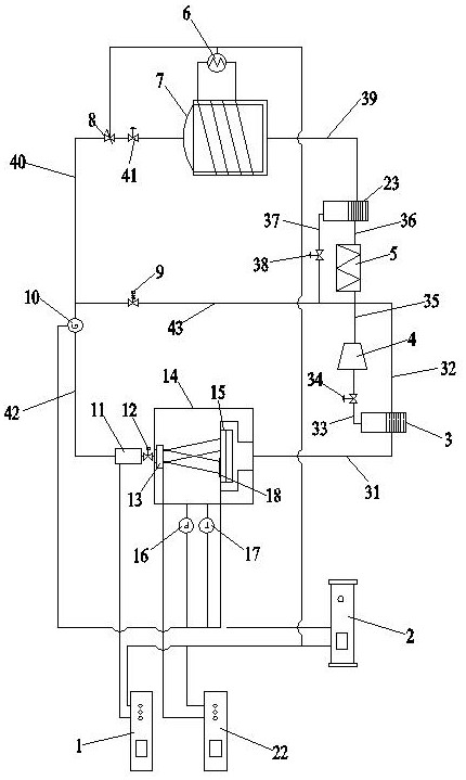
[0038] Such as figure 1 Shown: In order to effectively solve the high-efficiency heat dissipation of high-power chips and improve cooling efficiency, the present invention includes a spray chamber 14 that can accommodate high-power chips to be dissipated, a charging chamber 11 that can make the cooling medium carry charges, and can communicate with the above-mentioned The spray chamber 14 and the charging chamber 11 are adapted to connect the cooling medium refrigeration cycle pipeline mechanism;

[0039] The charging chamber 11 is located above the spray chamber 14 and the charging chamber 11 communicates with the micro-channel nozzle 13 in the spray chamber 14, and the spray chamber 14 is provided with a heat sink that can contact and cooperate with the high-power chip to be dissipated 15, the heat sink 15 is located directly below the microchannel nozzle 13...


PUM


Abstract

The invention relates to an electrostatic flash micro-spray circulating cooling system for heat dissipation of high-power chips, which includes a spray chamber, a charging chamber and a cooling medium refrigeration circulation pipeline mechanism; through the cooling medium refrigeration circulation pipeline mechanism, the liquid The cooling medium is sent into the charging chamber, and the charged droplets obtained through the charging chamber can enter the micro-channel nozzles of the spray chamber, so that the charged droplets can be deposited on the target surface under the action of the spray droplet electric field through the micro-channel nozzles. The surface of the heat sink, the cooling medium after cooling the heat sink is returned to the cooling medium refrigeration cycle pipeline mechanism, so that the current temperature of the heat sink collected by the heat sink temperature sensor is consistent with the preset target temperature in the circulating cooling controller consistent. The invention can effectively solve the high-efficiency heat dissipation of high-power chips, improve cooling efficiency, reduce system volume, and meet the technical requirements for miniaturization, integration and high reliability of cooling systems in the fields of national defense and aerospace.

Description

technical field [0001] The invention relates to a circulating cooling system, in particular to an electrostatic flash micro-spray circulating cooling system used for heat dissipation of high-power chips, and belongs to the technical field of chip heat dissipation. Background technique [0002] Electronic devices of high-power chips are widely used in aerospace, national defense, industrial and agricultural production, and biomedical fields due to their advantages of long life, high reliability, small size, and light weight. With the continuous improvement of chip power density, the continuous reduction of heat dissipation area, and the special application requirements of miniaturization, integration and light weight in the aerospace field, the power density of high-power chips has exceeded 500 W / cm 2 , which is equivalent to the heat generated by friction between the aircraft and the high-speed airflow when it returns to the atmosphere. The famous 10 ºC rule points out that...

Claims


Application Information

Patent Timeline
Patent Type & Authority Patents(China)
IPC IPC(8): H01L23/427
CPCH01L23/427
Inventor 田加猛王军锋张闫陈斌周致富
Owner 常州江苏大学工程技术研究院
Learn More