Supercharge Your Innovation With Domain-Expert AI Agents!

Biogas slurry and biogas residue multi-stage treatment device and method

A processing device and biogas residue technology, which is applied in the directions of organic fertilizers and climate change adaptation, can solve the problems of difficult promotion of biogas fermentation, and achieve the effect of reasonable overall structure design and avoiding foul odors.

Active Publication Date: 2020-08-18
GUANGDONG UNIV OF PETROCHEMICAL TECH
View PDF11 Cites 0 Cited by
  • Summary
  • Abstract
  • Description
  • Claims
  • Application Information

AI Technical Summary

Problems solved by technology

[0004] However, due to the complicated waste cleaning process after biogas fermentation, it is difficult to promote biogas fermentation.

Method used


Image

  • Biogas slurry and biogas residue multi-stage treatment device and method
  • Biogas slurry and biogas residue multi-stage treatment device and method
  • Biogas slurry and biogas residue multi-stage treatment device and method

Examples


Embodiment 1

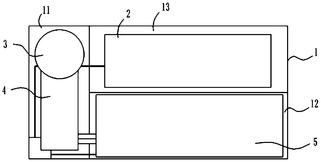
[0036] Embodiment 1: as figure 1 , 2 A biogas slurry and biogas slag multi-stage treatment device shown in . 1 Internally used for solid-liquid separation equipment to further ferment the liquid treated with biogas residue and biogas slurry 2; the equipment shell 1 includes a first cavity 11, a second cavity 12, a third cavity 13, and the second cavity The second cavity 12 and the third cavity 13 are arranged side by side to form a connecting cavity, and the first cavity 11 is arranged side by side with the connecting cavity;

[0037] The solid-liquid separation equipment includes a first separation equipment 3, a second separation equipment 4, and a third separation equipment 5 connected in sequence;

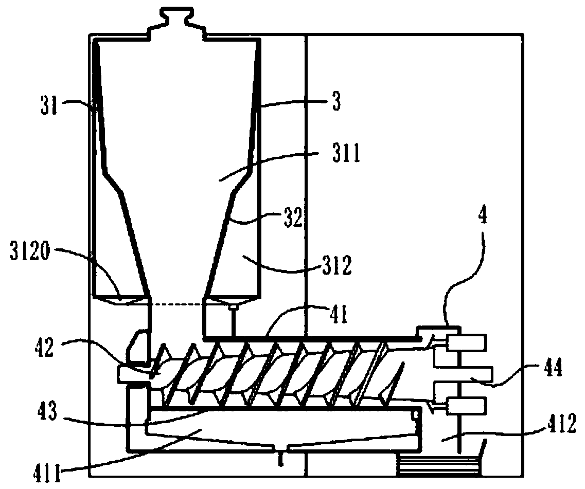
[0038] Such as figure 1 , 2 As shown, the first separation device 3 is installed in the first cavity 11; the first separation device 3 includes a cylindrical feed tank 31, and a first filter assembly 32 arranged inside the feed tank 31; the first filter The component 32 divi...

Embodiment 2

[0045] Embodiment 2: Different from Embodiment 1: as Figure 4 , 5 As shown, the first separation device 3 also includes an auxiliary filter assembly 33 for buffering. The auxiliary filter assembly 33 is installed on the feed tank 31 and is located inside the solid chamber 311; The first installation assembly 331 on the top, and the first slow flow plate assembly 332 arranged at the lower end of the first installation assembly 331; the first slow flow plate assembly 332 includes three first buffer plates 3321, and is used for three first buffer plates The first connecting rod 3322 connected between the plates 3321; the first installation component 331 adopts 2 sets of hanging steel ropes;

Embodiment 3

[0046] Embodiment 3: Different from Embodiment 1: as Figure 6 , 7 As shown, the first separation device 3 also includes an auxiliary filter assembly 33 for buffering. The auxiliary filter assembly 33 is installed on the feed tank 31 and is located inside the solid chamber 311; The second installation assembly 333 on the top, and the second slow flow plate assembly 334 arranged at the lower end of the second installation assembly 333; the second installation assembly 333 uses two installation rods, and the second slow flow plate assembly 334 adopts a conical structure for buffering block, and the second slow flow plate assembly 334 is located at the discharge port of the feed tank 31 .


PUM


Abstract

The invention discloses a biogas slurry and biogas residue multistage treatment device and method. The biogas slurry and biogas residue multistage treatment device comprises an equipment shell, solid-liquid separation equipment arranged in the equipment shell and used for solid-liquid separation of biogas slurry and biogas residues, and fermentation equipment arranged in the equipment shell and used for further fermenting liquid obtained after biogas slurry and biogas residues are treated by the solid-liquid separation equipment; the solid-liquid separation equipment comprises first separationequipment, second separation equipment and third separation equipment which are connected in sequence; by means of the first separation equipment, the second separation equipment and the third separation equipment, multi-stage solid-liquid separation of biogas slurry and biogas residues which are waste obtained after biogas fermentation is achieved, separation of the biogas residues and the biogas slurry is achieved more thoroughly, and special utilization of the biogas residues and the biogas slurry can be achieved.

Description

technical field [0001] The invention relates to the technical field of biogas slurry and residue treatment and utilization equipment, in particular to a multi-stage treatment device and method for biogas slurry and residue. Background technique [0002] Biogas fermentation refers to the process in which organic substances are decomposed and metabolized by various microorganisms under certain moisture, temperature and anaerobic conditions, and finally form flammable mixed gases such as methane and carbon dioxide. The biogas fermentation system is based on the principle of biogas fermentation, with the goal of energy production, and finally realizes the comprehensive utilization of biogas, biogas slurry and biogas residue. [0003] As early as 2007, my country began to vigorously develop and support the construction of biogas digesters, especially focusing on rural areas. And in order to increase promotion efforts, the government also introduced a series of subsidy measures. ...

Claims


Application Information

Patent Timeline
Patent Type & Authority Applications(China)
IPC IPC(8): C05F9/02C05F9/04
CPCC05F9/02C05F9/04Y02A40/20Y02E50/30
Inventor 张冬青牛晓君吕梦雨郭华芳唐志华刘敏茹张荔
Owner GUANGDONG UNIV OF PETROCHEMICAL TECH
Features
  • R&D
  • Intellectual Property
  • Life Sciences
  • Materials
  • Tech Scout
  • Unparalleled Data Quality
  • Higher Quality Content
  • 60% Fewer Hallucinations
Learn More