
Temperature measuring method of electromagnetic induction temperature measuring device

A temperature measuring device and electromagnetic induction technology, applied in the field of temperature measurement, can solve problems such as easy to generate errors, test data errors, and oscillating circuits that cannot achieve standard resonance, etc., to achieve the effect of reducing errors and small errors

Pending Publication Date: 2020-08-18
肇庆市热点智能家居科技有限公司
View PDF0 Cites 0 Cited by
  • Summary
  • Abstract
  • Description
  • Claims
  • Application Information

AI Technical Summary

Problems solved by technology

Contact temperature measurement is prone to delay
[0003] In the existing temperature measurement method, the resonant frequency changes after heating, causing the resonant frequency of the resonant circuit to shift. If the oscillation is driven by a fixed frequency method, the oscillating circuit cannot achieve standard resonance, and the test data is prone to errors
prone to errors

Method used


Image

  • Temperature measuring method of electromagnetic induction temperature measuring device
  • Temperature measuring method of electromagnetic induction temperature measuring device
  • Temperature measuring method of electromagnetic induction temperature measuring device

Examples


Embodiment 1

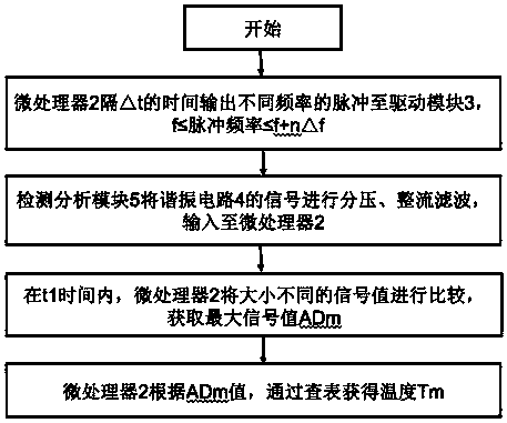
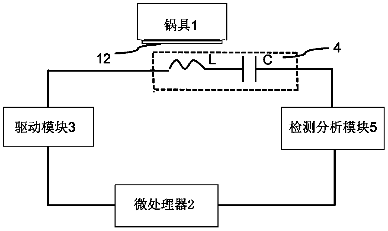
[0044] Such as figure 1 As shown, an electromagnetic induction temperature measuring device provides a pot 1, the pot 1 is provided with a temperature sensing layer 12, and the electromagnetic induction temperature measuring device includes a microprocessor 2, a drive module 3, a resonance Circuit 4 and detection analysis module 5;

[0045] The microprocessor 2 is used to output the pulse driving signal and the signal of the analysis and processing detection analysis module 5, and the microprocessor 2 has an AD port;

[0046] The driving module 3 is used to amplify the pulse signal output by the microprocessor 2 to drive the pulse signal;

[0047] The resonant circuit 4 is used to convert the electrical signal into a magnetic field, including an inductance and a capacitor, both of which are at least one, and the resonant circuit 4 and the temperature-sensing layer 12 generate a coupling impedance;

[0048] The detection and analysis module 5 is used to detect the electrical si...

Embodiment 2

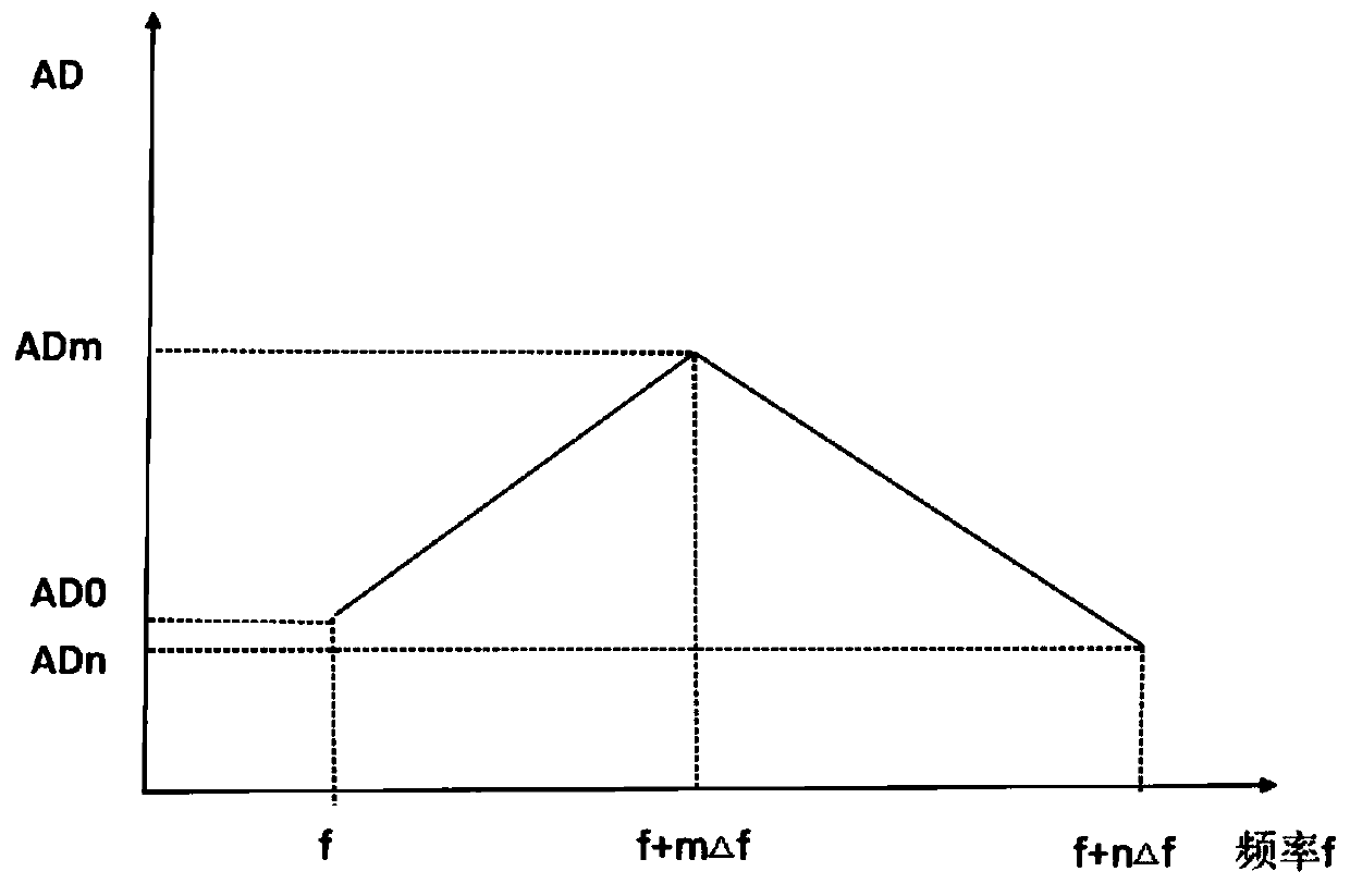
[0065] The difference from Embodiment 1 is that the initial frequency of the pulse is f+n△f, the signal value is ADn, and the frequency of the output pulse of the microprocessor 2 is gradually reduced, gradually reducing △f each time, when the frequency of the pulse is f , the signal value is AD0. image 3 It is a linear relationship diagram between the pulse frequency and the signal value, and the relationship between the pulse frequency and the signal value can also be a curve.

Embodiment 3

[0067] The difference from Embodiment 1 is that 0.01KHz≤Δf≤0.5kHz.


PUM

PropertyMeasurementUnit
Diameteraaaaaaaaaa
Lengthaaaaaaaaaa
Diameteraaaaaaaaaa

Abstract

The invention relates to a temperature measurement method for an electromagnetic induction temperature measurement device, and the method comprises the following steps that a microprocessor outputs pulses with different frequencies to a drive module at an interval of t, and the drive module drives a resonance circuit to oscillate; a detection and analysis module is used for connecting an output signal to the microprocessor through voltage division, rectification and filtering, and recording signal values with different sizes measured by pulses with different frequencies; in the t1 period of time, a microprocessor compares the signal values with different sizes, and selects the maximum signal value as ADm, wherein the pulse frequency corresponding to the ADm is f + m*delta(f); and calculating a real-time temperature value Tm according to the ADm. According to the control method, the driving frequency is adjusted in real time, the resonance circuit in the temperature measuring device isaccurately mastered to reach a resonance point, errors among devices are reduced, the problems of resonance frequency change after heating, resonance frequency deviation of the resonance circuit and errors are solved, and the purpose of accurate temperature measurement is achieved.

Description

technical field [0001] The present invention relates to the technical field of temperature measurement, more specifically, to an electromagnetic induction temperature measurement device, and also to a method for electromagnetic induction temperature measurement. Background technique [0002] The existing electromagnetic heating device is equipped with a temperature sensor, the most common is to install a temperature measuring probe directly near the panel, through which the temperature of the panel can be detected, and then controlled by the circuit to control the temperature of the panel within a certain range, Although this method can realize the detection of temperature, there are still many deficiencies. For example, the temperature sensor has a certain hysteresis in the detection of temperature. Its lifespan is greatly shortened. Contact temperature measurement is prone to delay. [0003] In the existing temperature measurement method, the resonant frequency changes a...

Claims


Application Information

Patent Timeline
IPC IPC(8): G01K7/16G01K7/24
CPCG01K7/16G01K7/245G01K2207/00G01K2219/00
Inventor 陈景超
Owner 肇庆市热点智能家居科技有限公司
Learn More