
Ophthalmic measurement system

A measurement system and ophthalmology technology, applied in medical science, eye testing equipment, diagnosis, etc., can solve problems such as high cost and complex structure, and achieve the effect of beautiful appearance, overcoming complex structure, and avoiding pressure.

Pending Publication Date: 2020-08-21
SHENZHEN CERTAINN TECH CO LTD
View PDF2 Cites 1 Cited by
  • Summary
  • Abstract
  • Description
  • Claims
  • Application Information

AI Technical Summary

Problems solved by technology

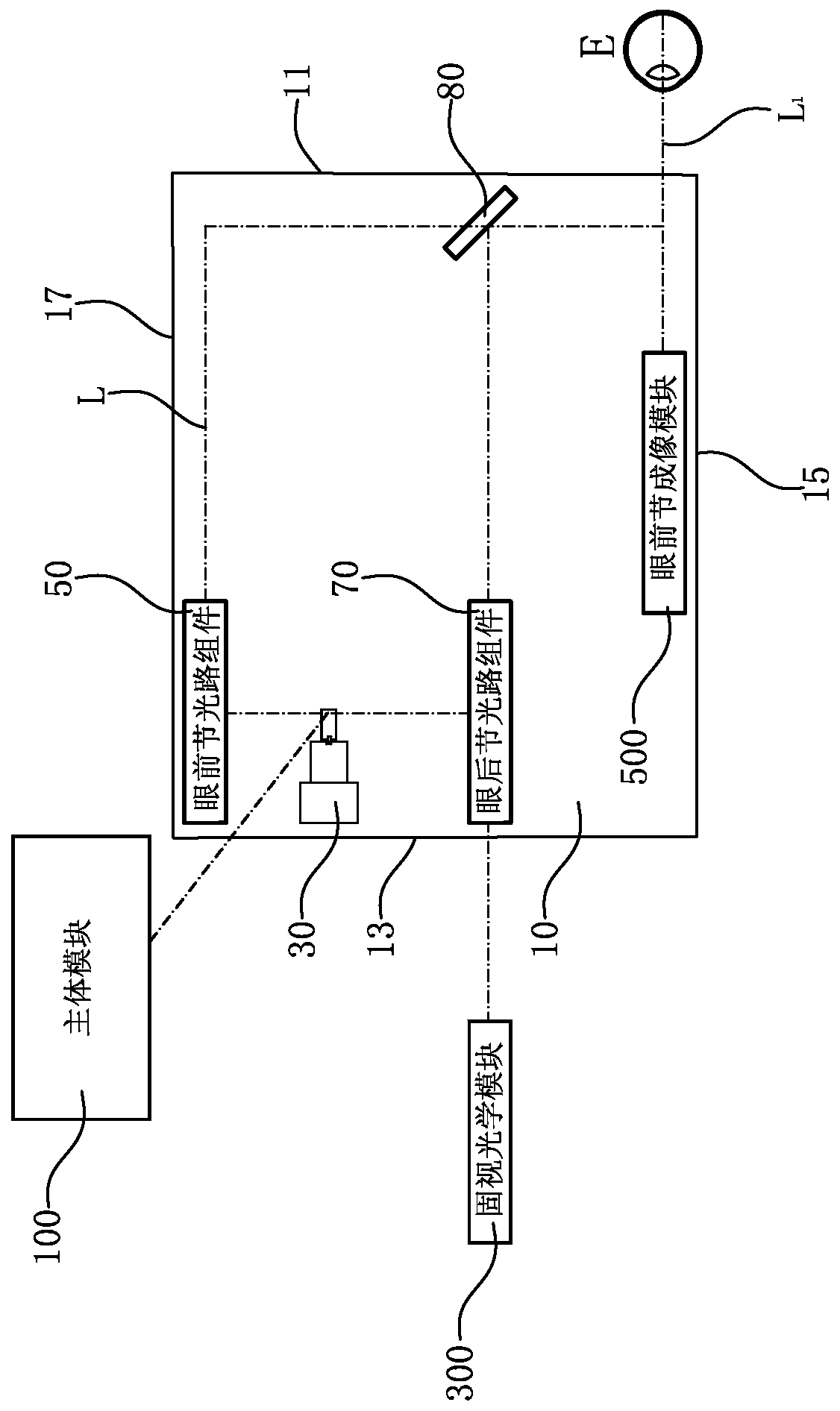
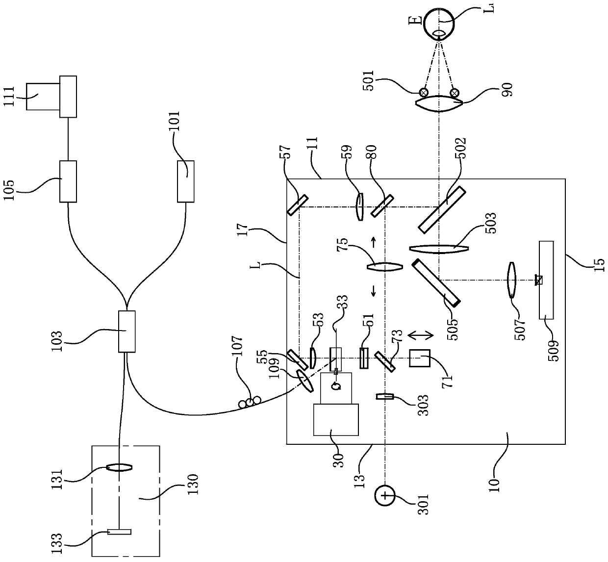
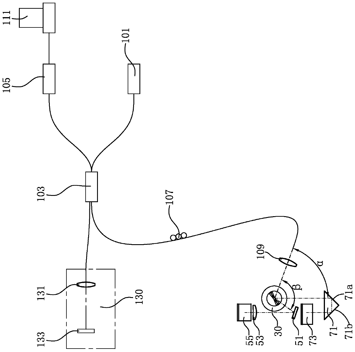
[0007] Based on OCT technology, the present invention provides an ophthalmology measurement system, which belongs to another technical solution that can switch between scanning the anterior segment and posterior segment of the eye to determine the axial length of the eye based on spectral domain OCT technology. It can also overcome the disadvantages of complex structure and high cost in the prior art

Method used


Image

  • Ophthalmic measurement system
  • Ophthalmic measurement system
  • Ophthalmic measurement system

Examples


Embodiment 1

[0081] This embodiment provides an ophthalmological measurement system (hereinafter referred to as "system") for detecting the eye E to be inspected, so as to determine the axial length of the eye E to be inspected. Preferably, the system can also determine multiple parameters of the inspected eye E, such as the corneal curvature of the inspected eye E, the depth of the anterior chamber of the eye, the white-to-white distance, and the pupil diameter.

[0082] Please refer figure 1 with figure 2 The system includes a main body module 100, a reference plane 10, a scanning plane (not shown), a switching scanning element 30, an anterior segment optical path assembly 50, a posterior segment optical path assembly 70, a beam splitting element 80, and the main optical axis L of the system. Preferably, the system further includes an eye lens 90, a fixation optical module 300, and an anterior segment imaging module 500.

[0083] figure 1 , figure 2 The dotted line indicates the main optica...

Embodiment 2

[0131] This embodiment provides an ophthalmological measurement system (hereinafter referred to as the "system"). Embodiment 1 is a basic embodiment of the present invention. For the sake of simplicity, the ophthalmological measurement system provided in this embodiment is similar to Embodiment 1, and will not be To repeat, the first embodiment is incorporated into this embodiment by reference.

[0132] The ophthalmic measurement system provided in this embodiment is used to detect the eye E to be inspected, so as to determine parameters such as the axial length of the eye E to be inspected. Please refer Figure 7 , The system includes a main body module 2100, a reference plane 210, a switching scanning element 230, an anterior segment optical path assembly 250, a posterior segment optical path assembly 270, and a beam splitting element 280. Please join Picture 8 Preferably, the system further includes an eye lens 290, a fixation optical module 2300, and an anterior segment imag...


PUM


Abstract

The invention discloses an ophthalmic measurement system for inspected eye detection. The system comprises a main body module, a reference plane, a switching scanning element, an anterior segment light path assembly, a posterior segment light path assembly and a light splitting element, the anterior segment light path assembly, the posterior segment light path assembly and the light splitting element are all arranged on the reference plane, and the switching scanning element can rotate around a fixed shaft, so that switching between the anterior segment light path assembly and the posterior segment light path assembly is realized, and the anterior segment and the posterior segment of a detected eye can be horizontally scanned. According to the invention, switching between anterior segmentscanning and posterior segment scanning of the detected eye can be realized based on the spectral domain OCT technology so as to determine the axial length of the detected eye, the defects of complexstructure and high cost in the prior art can be overcome, and horizontal scanning can be realized.

Description

Technical field [0001] The invention belongs to the field of ophthalmic examination equipment, and in particular relates to an ophthalmic measurement system. Background technique [0002] Cataract surgery, corneal refractive surgery, and effective prevention and treatment of adolescent myopia all require accurate measurement of multiple parameters of the eye, such as the curvature of the anterior and posterior surface of the cornea, the thickness of the cornea, the depth of the anterior chamber, the thickness of the lens, the curvature of the front and back surface of the lens, the length of the eye axis, White to white distance, pupil diameter, etc. In the prior art, the most widely used technology for obtaining the multiple parameters is ultrasonic technology, but its measurement accuracy is low. [0003] In view of the shortcomings of ultrasound technology, people have developed an ophthalmological measurement system based on OCT (Optical Coherence Tomography) technology to obt...

Claims


Application Information

Patent Timeline
Patent Type & Authority Applications(China)
IPC IPC(8): A61B3/10A61B3/14A61B3/107A61B3/11
CPCA61B3/102A61B3/14A61B3/107A61B3/112
Inventor 蔡守东郭曙光吴蕾代祥松李鹏王辉
Owner SHENZHEN CERTAINN TECH CO LTD
Learn More