High-energy beam additive manufacturing forming device and forming method

A technology of additive molding and additive manufacturing, which is applied in the direction of additive manufacturing, additive processing, and energy efficiency improvement. It can solve problems such as residual stress, microscopic crack spheroidization, reduced additive molding control effect, and difficult tissue control. Achieve the effects of improving laying efficiency, improving control effect, and improving molding quality

Inactive Publication Date: 2020-08-21
SHANGHAI UNIV
View PDF7 Cites 9 Cited by
  • Summary
  • Abstract
  • Description
  • Claims
  • Application Information

AI Technical Summary

Problems solved by technology

[0003] 3D printing technology has many advantages, but there are still deficiencies in its formed parts. Even if the components formed by 3D printing technology have high density, it is difficult to avoid some inherent defects in the process of forming parts, such as difficult to control the structure, residual stress, microscopic cracks, Formation of defects such as spheroidization and porosity
The authorized patent CN105522153B discloses a device for electromagnetic field-assisted laser additive manufacturing. The bottom of the base is an insulating heat dissipation layer, and the bottom of the insulation heat dissipation layer is a magnetic field generator. The magnetic field generator is equipped with a plurality of magnetic rods. The rod generates a high-frequency magnetic field to oscillate and stir the molten pool at different positions to improve the internal quality of the additively manufactured parts. However, since the magnetic induction lines emitted by the raw magnetic rod are all divergent in the radial direction of the raw magnetic rod, the magnetic field Less control over additive molding

Method used


Image

  • High-energy beam additive manufacturing forming device and forming method
  • High-energy beam additive manufacturing forming device and forming method
  • High-energy beam additive manufacturing forming device and forming method

Examples


Embodiment 1

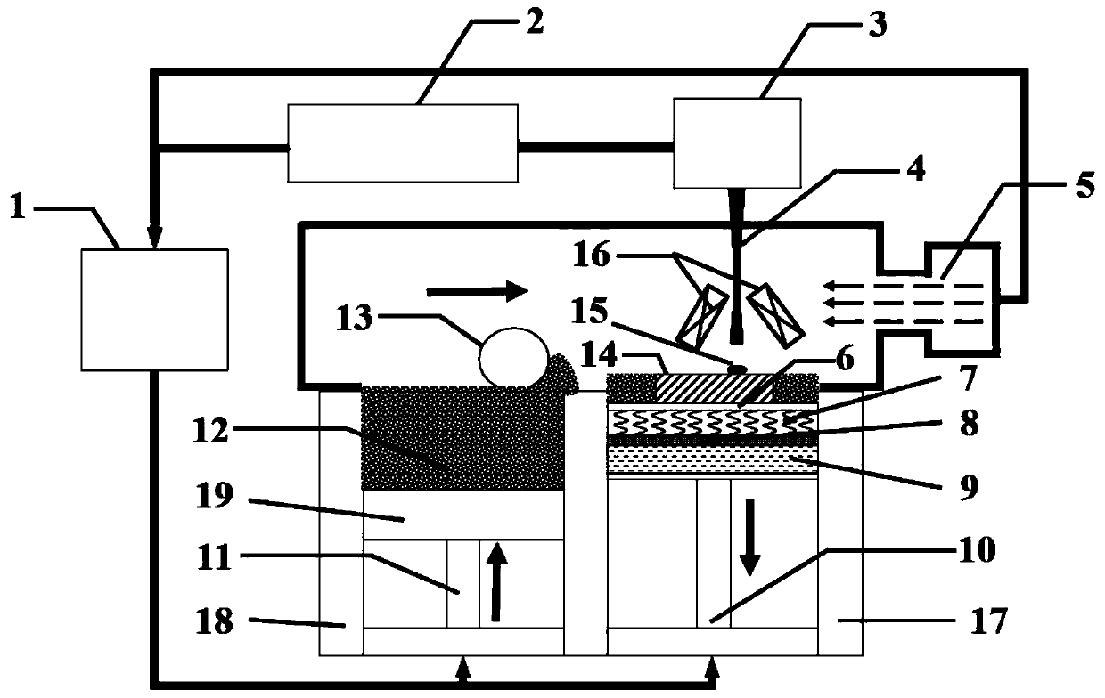
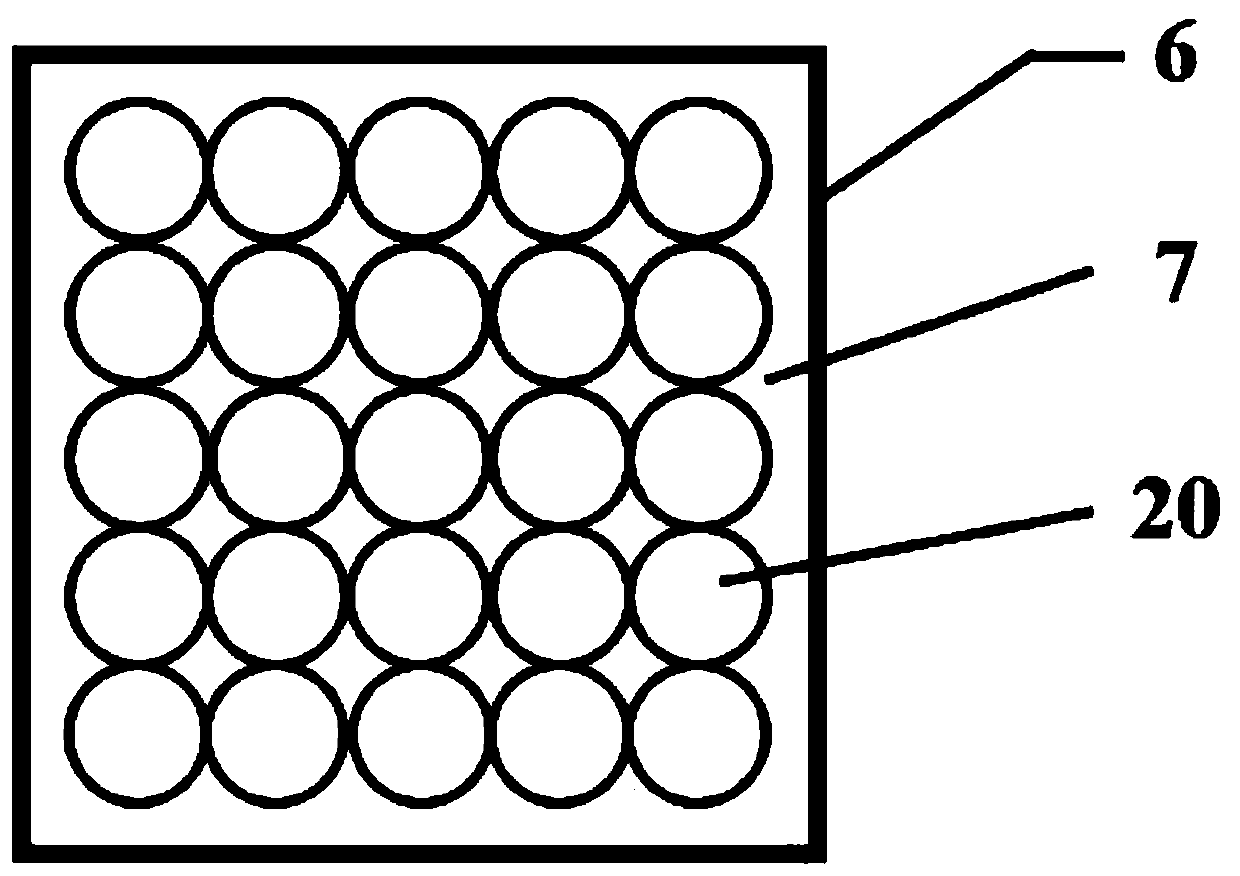
[0037] Such as Figure 1-Figure 3 As shown, the present embodiment provides a magnetic field unit for auxiliary additive molding, including a first magnetic field generating device 7, the first magnetic field generating device 7 includes an induction coil 20 arranged below the molten pool 15, and the magnetic flux generated by the induction coil 20 The induction line can pass through the molten pool 15 , and at any moment, the molten pool 15 formed by the melting of the material 12 to be processed is located in the area where the induction coil 20 emits concentrated magnetic induction lines.

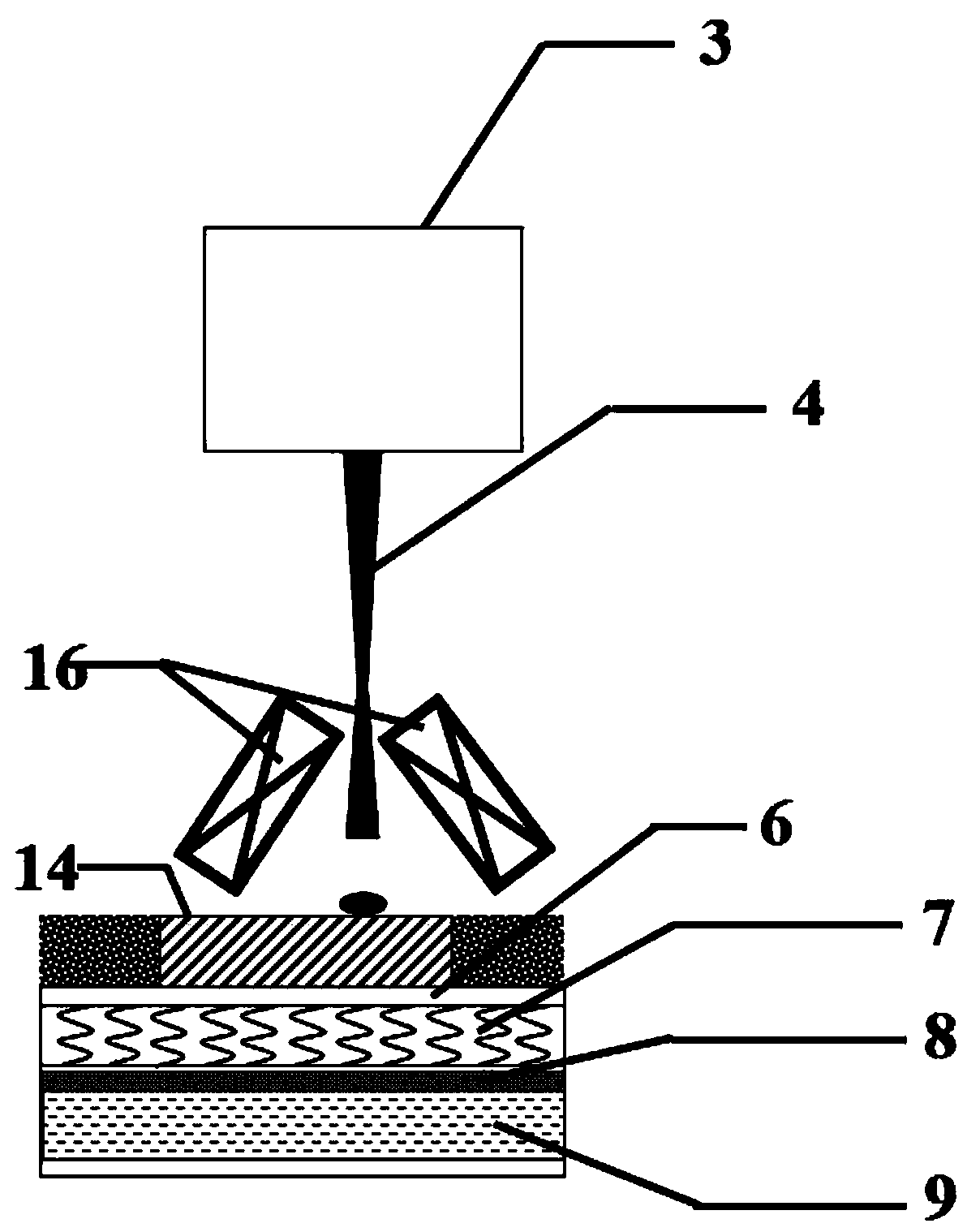
[0038] Before additive molding, the induction coil 20 is connected to a DC power supply or an AC power supply to generate a steady magnetic field or an alternating magnetic field, and the middle part of the induction coil 20 generates clustered magnetic lines, which are drawn from the bottom of the molding surface of the molten pool 15 through. When performing additive molding, the mate...

Embodiment 2

[0040] Such as Figure 1-Figure 3 As shown, this embodiment provides a magnetic field unit for auxiliary additive molding. On the basis of Embodiment 1, the magnetic field unit for auxiliary additive molding in this embodiment also has the following characteristics:

[0041] In order to make the magnetic field where the molten pool 15 is located uniform, the induction coil 20 arranged below the molten pool 15 is perpendicular to the surface where the molten pool 15 is located, so that the clustered magnetic lines generated by the induction coil 20 can all penetrate from the bottom of the molten pool 15, and the induction coil 20 The number of settings can be one or more. When the number of induction coils 20 is set to one, the forming range of the molten pool 15 is located within the inner diameter of the induction coil 20. When the number of induction coils 20 is set to multiple, more Each induction coil 20 is arranged in an array along the transverse direction and the longit...

Embodiment 3

[0044] Such as Figure 1-Figure 3 As shown, this embodiment provides a high-energy beam additive manufacturing forming device. On the basis of Embodiment 2, the high-energy beam additive manufacturing forming device of this embodiment also has the following characteristics:

[0045] The device for high-energy beam additive manufacturing molding includes a magnetic field unit for auxiliary additive molding, a molding base 6, and a high-energy beam generating device; the molding base 6 is a hollow box-shaped structure, and the upper surface of the molding base 6 is used for additive molding. The molding surface is flat, and the second magnetic field generating device 16 is arranged above the molding surface. In the molding base 6, a first magnetic field generating device 7 and a water cooling device 9 for cooling the first magnetic field generating device 7 are sequentially arranged from top to bottom. The heat dissipation layer 8 , the insulating heat dissipation layer 8 and t...


PUM


Abstract

The invention discloses a high-energy beam additive manufacturing forming device and method. The device comprises a magnetic field unit for assisting additive forming, and further comprises a formingbase for placing a to-be-processed material, and a high-energy beam generation device which emits a high-energy beam, acts on the to-be-processed material, and forms a molten pool. The magnetic fieldunit comprises a first magnetic field generating device, and the first magnetic field generating device comprises an induction coil arranged below the molten pool. The first magnetic field generatingdevice is detachably arranged below the surface, used for containing the to-be-processed material, of the forming base; a second magnetic field generating device is arranged above the forming base; the induction coil is arranged below the molten pool, and the molten pool is located in the area, where the clustered magnetic induction lines are emitted, of the induction coil, so that the clustered magnetic induction lines penetrate through the molten pool, therefore, the magnetic field intensity of the molten pool is concentrated, the control effect of the magnetic field on additive forming is improved, and the control efficiency of the magnetic field unit on the molten pool is improved.

Description

technical field [0001] The invention relates to the field of metal additive manufacturing process control, in particular to a high-energy beam additive manufacturing molding device and molding method. Background technique [0002] Additive manufacturing technology, also known as 3D printing technology, is based on the principle of layering and superposition, using computers to control the trajectory of high-energy laser beams / electron beams / arcs, and using high-energy laser beams / electron beams / arcs to melt metal powder. After the high-energy beam melts the metal powder, the molten metal forming the molten pool undergoes rapid cooling and solidification. The entire additive manufacturing is the forming step of the high-energy beam spot movement from point to surface, and then from surface to body. This point-line-surface-body integrated processing method has unique advantages in manufacturing components with complex shapes. Due to its high material utilization rate, short ...

Claims


Application Information

Patent Timeline
Patent Type & Authority Applications(China)
IPC IPC(8): B22F3/105B33Y10/00B33Y30/00B33Y50/02
CPCB33Y30/00B33Y10/00B33Y50/02B22F2003/1053B22F2202/05B22F2202/07B22F10/00B22F12/00B22F10/28B22F10/30Y02P10/25B22F2999/00B22F12/20B22F12/40B22F12/45B22F12/50B22F12/41B22F12/30B22F12/60B22F2998/10
Inventor 任忠鸣王江陈超越刘伟赵睿鑫帅三三胡涛
Owner SHANGHAI UNIV
Why Eureka
Try Eureka