
Microcatheter withdrawal force test method and test system

A testing method and testing system technology, which is applied in the testing of mechanical components, force/torque/power measuring instruments, testing of machine/structural components, etc., and can solve the problem that microcatheters cannot be judged in a static environment, and microcatheters cannot be pulled out , blood vessel rupture and bleeding, etc., to avoid potential risks, avoid damage, and achieve the effect of good tube removal performance

Active Publication Date: 2020-10-13
SUZHOU HENRUI DISHENG MEDICAL CO LTD +1
View PDF8 Cites 0 Cited by
  • Summary
  • Abstract
  • Description
  • Claims
  • Application Information

AI Technical Summary

Problems solved by technology

However, there may be hidden dangers in the reflowed glue, for example, it will stick to the microcatheter, so that the microcatheter cannot be pulled out, and even cause the risk of blood vessel rupture and bleeding during extubation. For example, the prior art CN110755694A discloses a head containing The double-coated detachable microcatheter also discloses the test method of using Onyx glue to detect the withdrawal force of the microcatheter, but this program is launched for the withdrawal force of the microcatheter head-end release coating, and its construction The test platform is set up to simulate the actual situation of the human blood vessel during the operation, and the embolic agent needs to flow back to the specified length, and the flow rate of the fluid needs to be controlled for dynamic simulation. This test method is already available in the finished product of the elutable microcatheter However, it is impossible to judge the adhesion of the distal end of the microcatheter to the embolic preparation in a static environment. When the microcatheter has not been developed, the test data obtained under static conditions are very important for microcatheters. The research and development of catheters and embolic preparations provide parameter basis and design direction, which has important guiding significance

Method used


Image

  • Microcatheter withdrawal force test method and test system
  • Microcatheter withdrawal force test method and test system
  • Microcatheter withdrawal force test method and test system

Examples


Embodiment Construction

[0046] The technical solutions of the present invention will be clearly and completely described below in conjunction with the accompanying drawings. Apparently, the described embodiments are some of the embodiments of the present invention, but not all of them. Based on the embodiments of the present invention, all other embodiments obtained by persons of ordinary skill in the art without making creative efforts belong to the protection scope of the present invention.

[0047] In the description of the present invention, it should be noted that the terms "center", "upper", "lower", "left", "right", "vertical", "horizontal", "inner", "outer" etc. The indicated orientation or positional relationship is based on the orientation or positional relationship shown in the drawings, and is only for the convenience of describing the present invention and simplifying the description, rather than indicating or implying that the referred device or element must have a specific orientation, ...


PUM


Abstract

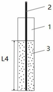
The invention discloses a microcatheter removal force test method and a test system. The test system comprises: a hose section, one end of which is clamped and the other end is open; a microcatheter section is cut from a catheter , the distal end of the microcatheter segment is used to insert into the hose segment, and the distal end of the microcatheter segment needs to reach the bottom where the hose segment is clamped; embolic preparation is used to fill the microcatheter The space between the catheter section and the hose section; the injection device is used to suck the embolic preparation and fill the embolic preparation in the space; the tensile test device is used to test the microcatheter section and the The maximum pulling force when the embolic preparation is separated. The test system and test method of the present invention are low in cost, have high convenience and operability, can meet daily test requirements, and have high accuracy in evaluating catheter withdrawal performance, effectively reduce the risk of catheter withdrawal, and improve the safety of surgery , medical devices and other fields are of great significance.

Description

technical field [0001] The invention relates to the technical field of medical device inspection, in particular to a method and system for testing the withdrawal force of a microcatheter. Background technique [0002] Brain arteriovenous malformation (AVM) and aneurysm are the most common clinical hemorrhagic cerebrovascular diseases, prone to neurological dysfunction, epileptic convulsions, rupture and bleeding, and have a very high disability rate and even fatality rate. The treatment methods of cerebral arteriovenous malformations and aneurysms mainly include: surgical resection, targeted radiation therapy and endovascular embolization. Surgical resection and directional radiation therapy have limitations, such as high cost of surgery, large damage to patients, and large side effects. Radiation therapy takes a long time and has high risks and side effects. With the rapid development of endovascular interventional therapy technology and the advancement of vascular imaging...

Claims


Application Information

Patent Timeline
Patent Type & Authority Patents(China)
IPC IPC(8): G01M13/00G01L5/00
CPCG01L5/0033G01M13/00
Inventor 朱晓瑛吴可沁黄海
Owner SUZHOU HENRUI DISHENG MEDICAL CO LTD
Learn More