
Sticker type sweat sensor with sweat collecting structure

A sensor and sweat technology, applied in the field of sweat sensors, can solve the problems of pollution and sweat sample evaporation, and achieve the effects of easy integration, less sample volume, and avoiding evaporation and pollution.

Pending Publication Date: 2020-08-25
NO 49 INST CHINESE ELECTRONICS SCI & TECH GRP
View PDF8 Cites 4 Cited by
  • Summary
  • Abstract
  • Description
  • Claims
  • Application Information

AI Technical Summary

Problems solved by technology

[0004] In order to solve the problem of evaporation and pollution of sweat samples in the existing sweat sensor, the present invention proposes a sticker-type sweat sensor with a sweat collection structure

Method used


Image

  • Sticker type sweat sensor with sweat collecting structure
  • Sticker type sweat sensor with sweat collecting structure
  • Sticker type sweat sensor with sweat collecting structure

Examples


specific Embodiment approach 1

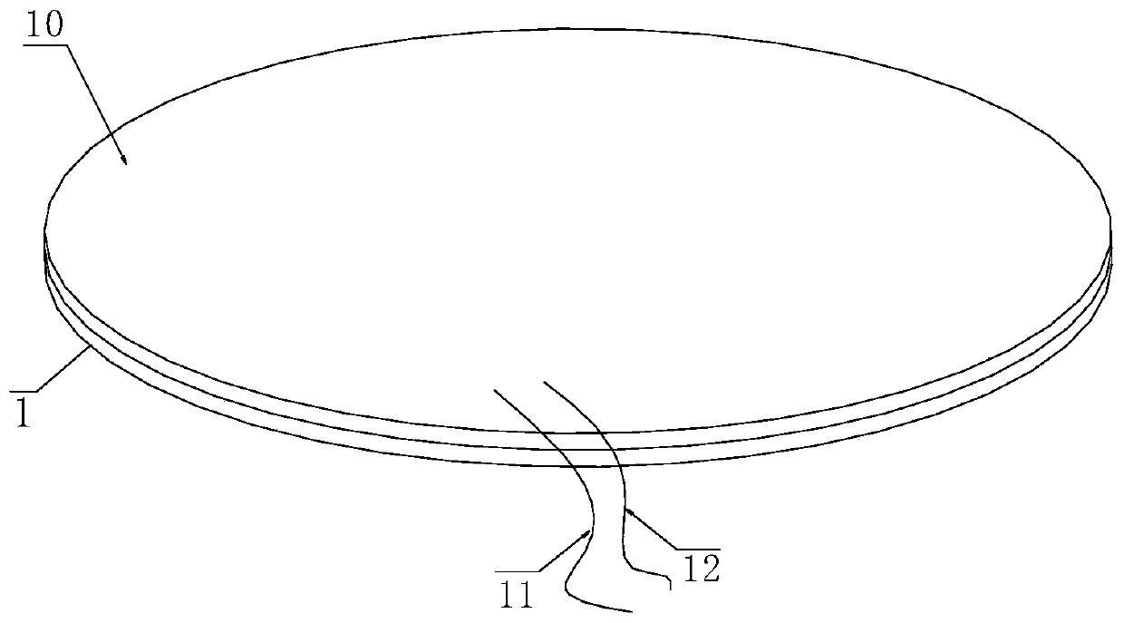
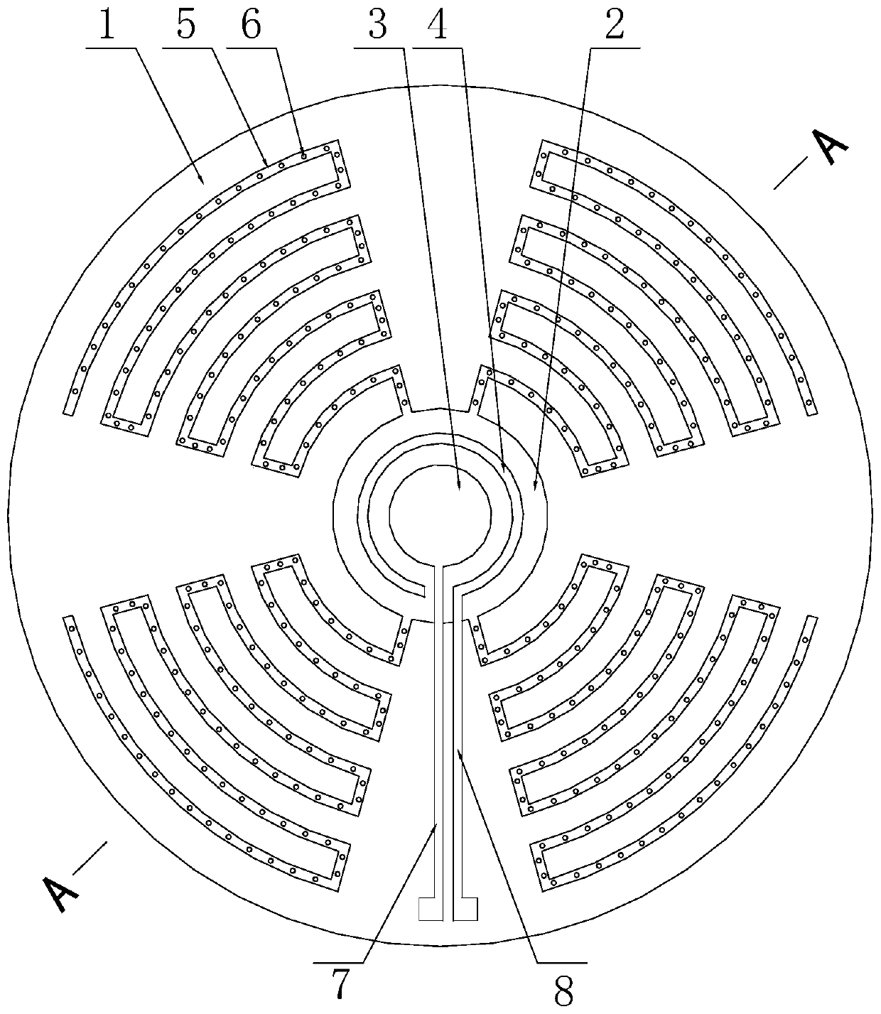
[0016] Specific embodiment one: the sticker type sweat sensor that this embodiment has sweat collection structure is made of sweat collection layer 1 and waterproof protective film layer 10, and sweat collection layer 1 is polyimide double-sided adhesive tape, waterproof protective film layer 10 Covering the upper surface of the sweat collection layer 1;

[0017] The center of the upper surface of the sweat collection layer 1 is provided with a microchamber 2, the microchamber 2 is a circular groove, and several microfluidic channels 5 are radially arranged around the microchamber 2, and the microfluidic channel 5 is a serpentine concave. Each microfluidic channel 5 is connected with the microchamber 2, and the bottom of the groove of the microfluidic channel 5 is provided with a capillary hole 6 penetrating the sweat collection layer 1; the center of the microchamber 2 is provided with a detection electrode, and the detection electrode The upper surface of the working electro...

specific Embodiment approach 2

[0020] Specific embodiment two: the difference between this embodiment and specific embodiment one is: the detection electrode is a two-electrode system composed of a working electrode 3 and a counter electrode 4, or the detection electrode is a working electrode 3, a counter electrode 4 and a reference electrode formed a three-electrode system.

specific Embodiment approach 3

[0021] Specific embodiment three: the difference between this embodiment and specific embodiment one or two is: the thickness of the sweat collection layer 1 is 90-110 μm, and the area is 0.5-1 cm 2 .


PUM

PropertyMeasurementUnit
thicknessaaaaaaaaaa
areaaaaaaaaaaa
volumeaaaaaaaaaa

Abstract

The invention provides a sticker type sweat sensor with a sweat collecting structure and relates to a sweat sensor. The invention aims at solving the evaporation and pollution problems of sweat samples of existing sweat sensors. The sticker type sweat sensor consists of a sweat collecting layer and a waterproof protecting film layer, wherein a plurality of microfluid channels communicating with amicro-cavity are radially formed in the periphery of the micro-cavity in the center of the upper surface of the sweat collecting layer, and capillary pores penetrating through the sweat collecting layer are formed in the bottoms of grooves of the microfluid channels; and a detecting electrode is arranged in the center of the micro-cavity, and a selective sense film is arranged on the upper surfaceof a working electrode in the detecting electrode. The sticker type sweat sensor sticks to the surface of skin in use, and the sweat is advantageously collected, conveyed and enriched by virtue of the capillary pores, the microfluid channels and the micro-cavity through a capillary phenomenon, so that the sample amount required by detection is little; and evaporation and pollution of a sweat sample can be effectively avoided by virtue of the waterproof protecting film layer. The sticker type sweat sensor has the advantages of flexibility, instantaneity, wearability and easiness in integrationand non-invasive detection.

Description

technical field [0001] The invention relates to a sweat sensor. Background technique [0002] With the rapid development of the field of flexible smart wearable sensing, home-based medical diagnosis has gradually entered our lives. Many wearable devices such as smart clothing, smart patches, and electronic tattoos are committed to achieving efficient and real-time human health. manage. Compared with physical signals such as heartbeat and breathing, the complex biomolecular information contained in sweat is closely related to human health. At the same time, sweat has become a potential development target of human biochemical sensors because of its advantages such as continuous secretion, non-invasive collection and stable microenvironment. [0003] Generally, the analysis of sweat components is mostly large-scale analysis equipment. Large-scale analysis equipment is not only bulky, but also expensive and cannot be worn. The rise of sweat sensors has made it possible for wea...

Claims


Application Information

Patent Timeline
Patent Type & Authority Applications(China)
IPC IPC(8): A61B10/00A61B5/00
CPCA61B10/0064A61B5/4266A61B5/6833
Inventor 王洋洋胡雨涵咸婉婷刘继江宋成君徐冬
Owner NO 49 INST CHINESE ELECTRONICS SCI & TECH GRP
Learn More