Neck nursing device
A nursing device and neck technology, which is applied in physical therapy, passive exercise equipment, medical science, etc., can solve problems such as chronic strain, and achieve the effects of reducing fatigue, simple structure, and reducing cervical deformation and cervical fatigue
- Summary
- Abstract
- Description
- Claims
- Application Information
AI Technical Summary
Problems solved by technology
Method used
Image
Examples
Embodiment 1
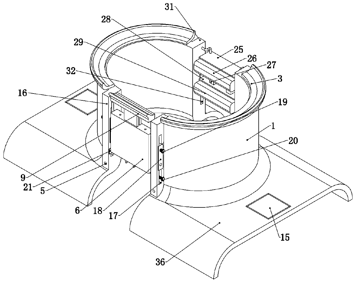
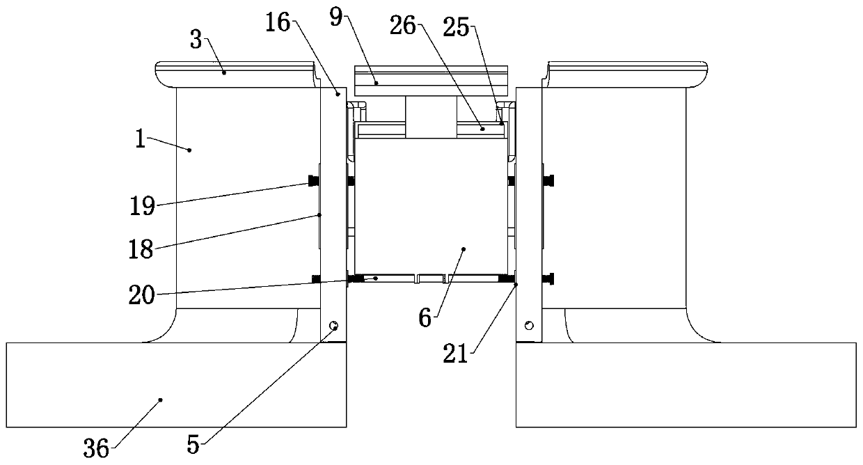
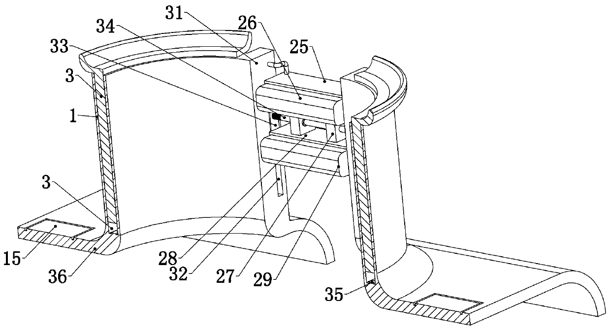
[0035] Embodiment 1, the present invention is a neck care device, comprising two semicircular guard plates 1, the two guard plates 1 can be combined and wrap the human neck, this is a common neck protection structure, the two guard plates 1 The boards 1 are respectively placed on both sides of the user's neck, because the human neck is not a complete cylinder, and considering the user's comfort, the two guard boards 1 will not be close to the skin of the user's neck, so the two The two guard plates 1 will not be completely assembled after merging, there is a space between the two ends of the two guard plates 1, and a guard plate air chamber 2 is provided in the two guard plates 1, and the two guard plates 1 are equipped with a guard plate gas chamber 2. The mandible support plate 3 slides up and down in the gas chamber 2 of the protective plate. The upper end of the mandibular support plate 3 is an arc-shaped plate. The head is raised to achieve the effect of pulling the cervi...
Embodiment 2
[0040] Embodiment 2. On the basis of Embodiment 1, this embodiment provides a specific structure in which the chin shell 6 is detachably connected between two guard plates 1. Specifically, refer to figure 1 , Figure 5 , one end of the two guard plates 1 is fixedly connected with a front wing plate 16, when the two guard plates 1 are put together, the two front wing plates 16 are parallel to each other, and the chin shell 6 is installed between the two front wing plates 16 Between, two described front wing plates 16 are provided with front chute 17, and front slider 18 is slidably connected in the two described front chute 17, and the two front sliders 18 are all slidably connected. Screw rods 19 are threaded, and specifically, two front sliders 18 are provided with threaded holes and the front screw rods 19 pass through the corresponding threaded holes and are threaded, and one end of the two front screw rods 19 can be connected with the When the chin shell 6 is in contact, ...
Embodiment 3
[0043] Embodiment 3. On the basis of Embodiment 2, this embodiment provides a specific structure to further slow down the speed at which the hydraulic oil enters the two side chambers 8 without affecting the structure of the hydraulic oil falling back to the initial liquid level. Specifically of, refer to Figure 4 , the two inner side walls of the two side chambers 8 are fixedly connected to the limit block 22, the lower end surface of the limit block 22 is the initial height of the liquid level, the setting of the two limit blocks 22 makes the hydraulic oil want to enter The space on the top of the limit block 22 must pass through the passage between the two limit fastenings. The diameter of this passage is far smaller than the diameter of the side chamber 8 under the limit of the two limit holes, thereby increasing the flow of hydraulic oil. Resistance, the upper ends of the four limit blocks 22 are uniformly connected with a wedge-shaped deflector block 23, and the incline...
PUM
 Abstract
Description
Claims
Application Information
 - R&D
- Intellectual Property
- Life Sciences
- Materials
- Tech Scout
- Unparalleled Data Quality
- Higher Quality Content
- 60% Fewer Hallucinations
Browse by: Latest US Patents, China's latest patents, Technical Efficacy Thesaurus, Application Domain, Technology Topic, Popular Technical Reports.
© 2025 PatSnap. All rights reserved.Legal|Privacy policy|Modern Slavery Act Transparency Statement|Sitemap|About US| Contact US: help@patsnap.com


