Convenient-to-clean anti-backflow and anti-leakage enemator

An anti-leakage, enema technology, applied in the direction of enema/irrigator, drug equipment, infusion set, etc., can solve the problems of anus or anorectal inner wall rupture, affecting the effect of enema operation, single function of the enema, etc. The progress of block enema operation, the stability of the connection seal, and the effect of reducing patient discomfort

Inactive Publication Date: 2020-08-25
孟凡玲
View PDF11 Cites 3 Cited by
  • Summary
  • Abstract
  • Description
  • Claims
  • Application Information

AI Technical Summary

Problems solved by technology

[0004] 1. The anal canal of the existing enema device is directly inserted into the patient's anorectum. Due to the contraction and extrusion of the anus, the anal canal is continuously pushed outward, resulting in greater damage to the perianal area due to friction during the insertion of the anal canal, and rupture of the inner wall of the anus or anorectum ;
[0005] 2. During the use of the existing enema device, there are hidden dangers that the enema liquid will seep out from the gap in the anus and flow back from the anal canal to the diversion tube, which will affect the effect of the enema operation;
[0006] 3. The existing enema device has a single function, and the exhaust operation before the enema operation needs to replace the connection between the diversion tube and the exhaust bag and the enema bag in turn. The operation process is cumbersome and time-consuming, resulting in long-term patient patience discomfort in the anal canal

Method used


Image

  • Convenient-to-clean anti-backflow and anti-leakage enemator
  • Convenient-to-clean anti-backflow and anti-leakage enemator
  • Convenient-to-clean anti-backflow and anti-leakage enemator

Examples


Embodiment Construction

[0037] In order to make the object, technical solution and advantages of the present invention clearer, the present invention will be further described in detail below in combination with specific embodiments and with reference to the accompanying drawings. It should be understood that these descriptions are exemplary only, and are not intended to limit the scope of the present invention. Also, in the following description, descriptions of well-known structures and techniques are omitted to avoid unnecessarily obscuring the concept of the present invention.

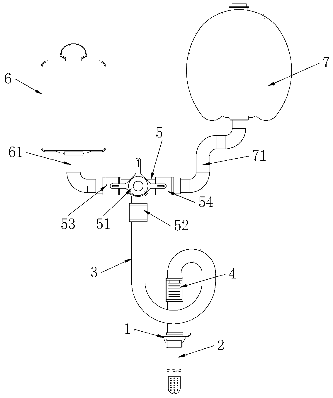
[0038] figure 1 It is a schematic diagram of the overall structure of the present invention;

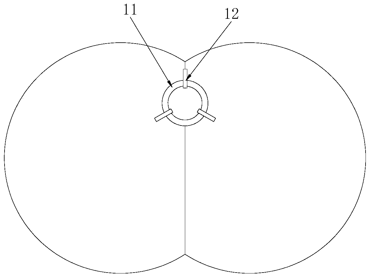
[0039] figure 2 It is a schematic diagram of the top view structure of the anal expansion device of the present invention;

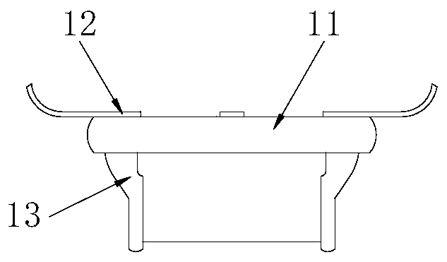
[0040] image 3 It is a schematic diagram of the front view structure of the anal expansion device of the present invention;

[0041] Figure 4 It is a structural schematic diagram of the anal canal...


PUM


Abstract

The invention belongs to the field of medical equipment, and particularly relates to a convenient-to-clean anti-backflow and anti-leakage enemator. The anti-backflow and anti-leakage enemator comprises an anal dilatation device mounted on the anus and an anal canal device left in the anus; the anal dilatation device comprises a perianal ring, a pull piece and an anal plug piece; the anal canal device and the anal dilatation device work cooperatively, the anal dilatation device can prevent the anus from contracting after dilating the anus, the anal canal device can be conveniently placed, frictional damage to the anus and the inner wall of the anorectum can be prevented, and the hidden danger of injury to a patient is reduced; the anal canal device and the anal dilatation device are designed in a split mode, the detaching is convenient, and the cleaning of the anal canal device and the anal dilatation device are convenient, and the anal canal device and the anal dilatation device are instable connection and sealing; leakage and backflow of clysis liquid can be prevented by matching with a flow limiting clamp installed on a flow guide tube, and a universal tube clamp is matched witha tube clamp A or a tube clamp B to form a channel through rotation of a three-way valve handle on a three-way device. The anorectum exhaust function and the enema function can be rapidly switched, consumed time is shortened, the clamping block enema operation progress is accelerated, and discomfort of a patient is reduced.

Description

technical field [0001] The invention relates to the field of medical equipment, in particular to an anti-reversal and anti-leakage enema that is easy to clean. Background technique [0002] Enema is a treatment method in which a catheter is inserted from the anus through the rectum to perfuse liquid into the colon to achieve laxative exhaust. It can stimulate intestinal peristalsis, soften and remove feces, and has the effect of cooling, inducing labor, diluting intestinal poisons, and reducing absorption. [0003] There are following problems in prior art: [0004] 1. The anal canal of the existing enema device is directly inserted into the patient’s anorectum. Due to the contraction and extrusion of the anus, the anal canal is continuously pushed outward, resulting in greater damage to the perianal area due to the friction during the insertion of the anal canal, and rupture of the anus or anorectal inner wall ; [0005] 2. During the use of the existing enema device, th...

Claims


Application Information

Patent Timeline
Patent Type & Authority Applications(China)
IPC IPC(8): A61M3/02A61M1/00
CPCA61M1/0058A61M3/0279A61M2210/1067A61M1/774A61M1/85A61M1/84A61M2210/005
Inventor 孟凡玲
Owner 孟凡玲
Why Eureka
Try Eureka