Cut-off equipment for superconductor lead screw

A superconductor and screw technology, which is applied in metal processing equipment, clamping, support, etc., can solve the problems of external thread damage of the screw, low breaking efficiency, and easy adhesion of debris and ash layer to the tool holder. Low truncation efficiency and temperature reduction effect

Active Publication Date: 2020-08-25
苏州科知律信息科技有限公司
View PDF8 Cites 4 Cited by
  • Summary
  • Abstract
  • Description
  • Claims
  • Application Information

AI Technical Summary

Problems solved by technology

[0004] In order to overcome the above-mentioned defects of the prior art, an embodiment of the present invention provides a cutting device for superconducting screw rods. The problem to be solved by the present invention is: the existing cutting devices for screw rods are basically manually cut off, and only one time Cutting off a screw, the cutting efficiency is low. At the same time, the positioning fixture of the existing screw cutting equipment directly fixes the external thread of the screw, which is easy to cause damage to the external thread of the screw. The debris dust layer is easy to adhere to the tool holder and affect the cutting effect of the superconductor screw rod

Method used


Image

  • Cut-off equipment for superconductor lead screw
  • Cut-off equipment for superconductor lead screw
  • Cut-off equipment for superconductor lead screw

Examples


Embodiment Construction

[0032] The following will clearly and completely describe the technical solutions in the embodiments of the present invention with reference to the accompanying drawings in the embodiments of the present invention. Obviously, the described embodiments are only some, not all, embodiments of the present invention. Based on the embodiments of the present invention, all other embodiments obtained by persons of ordinary skill in the art without making creative efforts belong to the protection scope of the present invention.

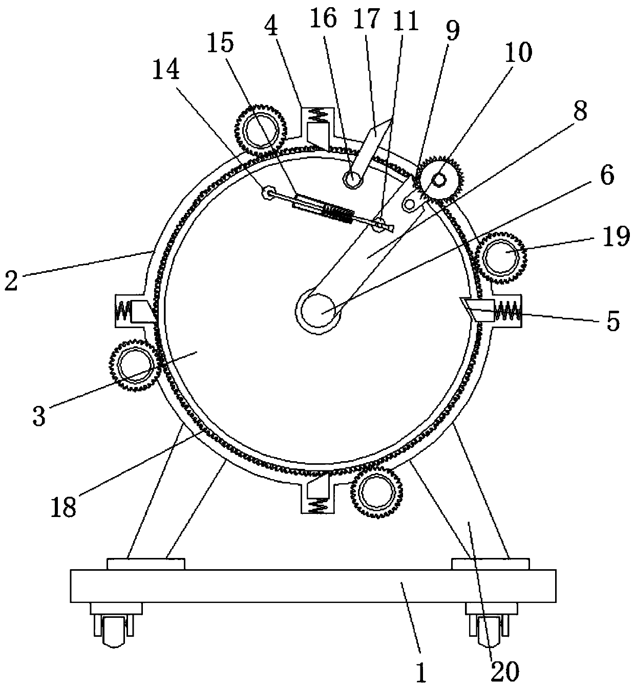
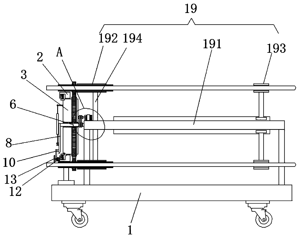
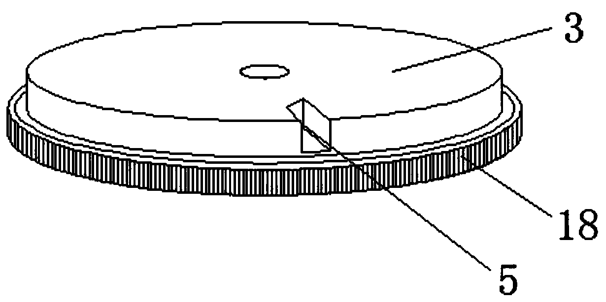
[0033]A cutting device for a superconductor screw according to an embodiment of the present invention includes a base 1, a turntable base 2 and an inner turntable 3, the turntable base 2 and the inner turntable 3 are both located above the base 1, and the inner turntable 3 is located on the turntable base The inside of the seat 2, and the rotation connection between the inner turntable 3 and the turntable base 2, the inner side of the turntable base 2 is fixedl...


PUM


Abstract

The invention discloses cut-off equipment for a superconductor lead screw, and particularly relates to the field of cut-off equipment. The cut-off equipment comprises a base, a rotary disc base and aninner rotary disc. The rotary disc base and the inner rotary disc are both located above the base, and the inner rotary disc is located on the inner side of the rotary disc base. The inner rotary disc and the rotary disc base are rotationally connected, and the periphery of the inner side of the rotary disc base is fixedly connected with limiting assemblies. Each limiting assembly comprises a strip-shaped groove, a first trapezoidal wedge block, a second trapezoidal wedge block, a third trapezoidal wedge block and a fourth trapezoidal wedge block. According to the cut-off equipment, by arranging the rotary disc base, the inner rotary disc, the limiting assemblies and a linkage mechanism, the problem that a traditional cut-off device of the superconductor lead screw is low in cut-off efficiency is solved; gas is sprayed to a cut-off machining position, and the temperature generated by cut-off machining can be effectively reduced; and meanwhile cutting dust in air around a cut-off tablecan be blown off to one side, and the situation that chipping dust layers generated in the cut-off process of the lead screw are attached to a tool rest, and the cut-off effect of the superconductorlead screw is influenced is avoided.

Description

technical field [0001] The invention relates to the technical field of cutting equipment, and more specifically, the invention relates to a cutting equipment for a superconductor threaded rod. Background technique [0002] Superconductor lead screw is the most commonly used transmission element in tool machinery and precision machinery. Its main function is to convert rotary motion into linear motion, or convert torque into axial repeated force, and at the same time, it has high precision, reversibility and high Features of efficiency. Due to its small frictional resistance, ball screws are widely used in various industrial equipment and precision instruments. [0003] In the process of reproducing the screw rod, equal-length cutting is usually required, but the cutting equipment of the existing screw rods is basically manually cut off, and only one screw rod can be cut at a time, and the cutting efficiency is low. The positioning fixture directly fixes the external thread...

Claims


Application Information

Patent Timeline
Patent Type & Authority Applications(China)
IPC IPC(8): B23D79/00B23Q11/00B23Q11/10B23Q3/00
CPCB23D79/00B23Q3/00B23Q11/005B23Q11/10B23Q2703/10
Inventor 安文光
Owner 苏州科知律信息科技有限公司
Why Eureka
Try Eureka