Shaft processing method

A processing method and induction heating technology, applied in the field of shaft processing, can solve the problems of melting, changing the shape and size of the shaft, and the shaft cannot be assembled and applied normally, and achieves uniform hardness, reduced force, and beneficial protection.

Active Publication Date: 2020-08-25
广西汇恒机械制造有限公司
View PDF14 Cites 1 Cited by
  • Summary
  • Abstract
  • Description
  • Claims
  • Application Information

AI Technical Summary

Problems solved by technology

[0005] In order to solve the problem that during the heat treatment process of the shaft, the junction of the circumferential side of the thick diameter section and the transition platform melts, changing the processing shape and size of the sha

Method used


Image

  • Shaft processing method
  • Shaft processing method
  • Shaft processing method

Examples


Embodiment Construction

[0043] The present invention will be further described in detail below in conjunction with the drawings and specific implementations:

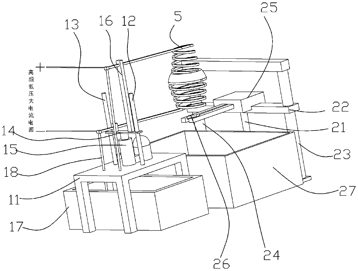
[0044] The embodiment of the shaft processing method of the present invention is specifically as follows, the device used in the shaft processing method is an induction heating treatment device, and the specific structure of the induction heating treatment device is as follows: figure 2 with Figure 7 Shown; including heating unit, load unit and cooling unit.

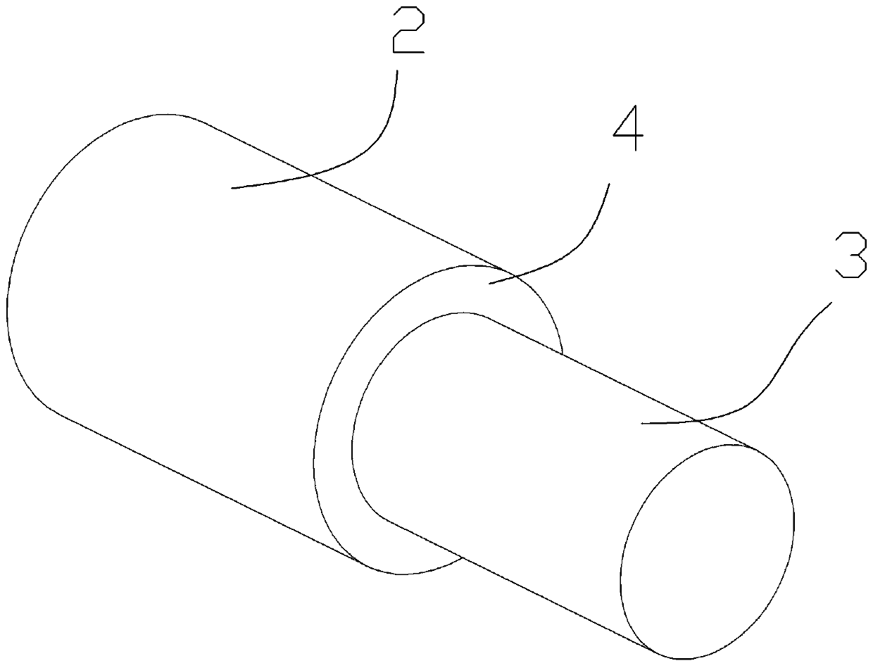
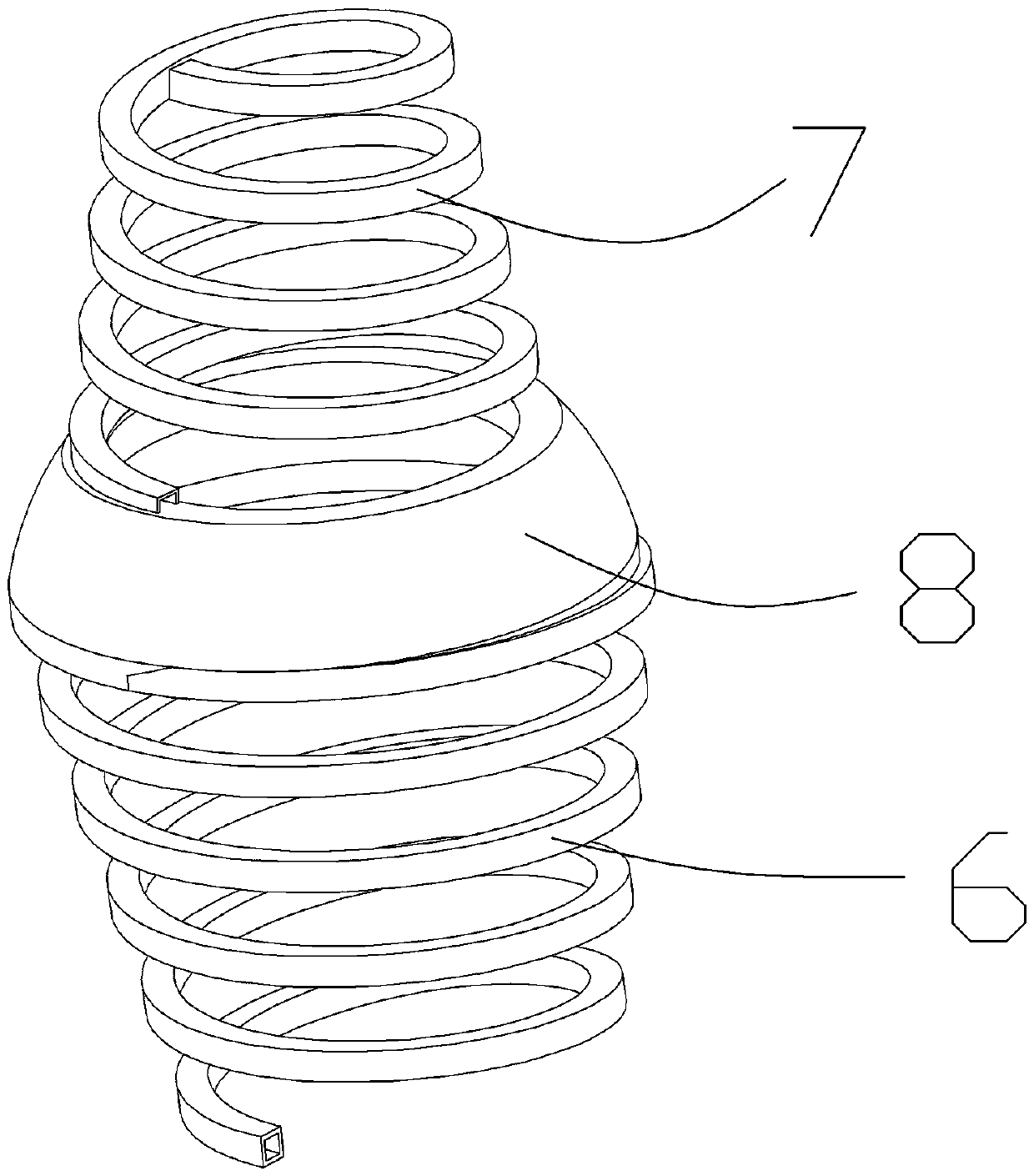
[0045] The heating unit includes an induction coil 5, a driving part for driving the induction coil 5 to move up and down, and a cooling part for cyclically cooling the induction coil 5. Such as image 3 with Figure 4 As shown, the induction coil 5 includes a large-diameter coil 6 for heating the large-diameter section 2 of the shaft 1, a small-diameter coil 7 for heating the small-diameter section 3 of the shaft 1, and a coil arranged in the large-diameter section The annular connecting ...


PUM


Abstract

The invention relates to a shaft processing method, which comprises the following specific steps of: inserting the lower end of a thin-diameter segment of a shaft into a cylindrical groove, and starting a finger air cylinder to clamp and fix the shaft; driving a second electric pushing rod to enable the lower end surfaces of the clamping fingers of the finger air cylinder and a quenching water tank to keep a distance of 10-30 cm; starting a first electric pushing rod to enable a top plate to downwards move to drive an induction coil to downwards move, inserting the shaft into the induction coil to enable the lower end surface of the induction coil and the upper end surface of the clamping fingers of the finger air cylinder to keep a distance of 0.5-4 cm; injecting cooling water into the circulation hole of the induction coil to circularly cool the induction coil, starting a high-frequency low-voltage big-current power supply to provide high-frequency low-voltage big current for the induction coil, carrying out induction heating on the shaft, and controlling time to be 2-5 minutes; and after the shaft is finished being heated, starting the finger air cylinder to open the clamping fingers, and enabling the shaft to fall into the quenching water tank from a gap between two clamping fingers. According to the shaft processing method, the problem in a shaft thermal treatment processthat a junction between a circumferential side surface of a thick-diameter segment and a transition platform is molten so as to change the processing shape and size of the shaft is solved.

Description

Technical field [0001] The invention belongs to the field of shaft processing, and specifically relates to a shaft processing method. Background technique [0002] Shafts are widely used in industrial production; shafts are mechanical parts used to support rotating parts to transmit rotation, torque or bending moment. When the shaft is used in some special working conditions, the core of the shaft is required to have a certain degree of toughness, while the circumferential surface of the shaft has a certain degree of hardness to adapt to the special working conditions. The specific structure of an application engineering machinery shaft is as figure 1 As shown, it includes a large diameter section 2 and a small diameter section 3, which are arranged in a transition platform 4 between the large diameter section 2 and the small diameter section 3; the transition platform 4 is perpendicular to the circumferential side of the large diameter section 2. [0003] When the shaft is used, ...

Claims


Application Information

Patent Timeline
IPC IPC(8): C21D1/10C21D1/64C21D9/28C21D11/00
CPCC21D1/10C21D1/64C21D9/28C21D11/005Y02P10/25
Inventor 刘胜徐勇杰
Owner 广西汇恒机械制造有限公司
Why Eureka
Try Eureka