Underneath pass type road culvert transition section foam light soil roadbed structure and construction method thereof

A foam lightweight soil and foam lightweight technology, applied in infrastructure engineering, roads, roads, etc., can solve the problems of narrow working surface, uneven lines, and reduce layer thickness, and achieve less construction site area requirements and roadbed bearing capacity. The effect of increasing strength and reducing foundation settlement value

Pending Publication Date: 2020-08-25
CREEC WUHAN SURVEY DESIGN & RES
View PDF0 Cites 1 Cited by
  • Summary
  • Abstract
  • Description
  • Claims
  • Application Information

AI Technical Summary

Problems solved by technology

When building subgrades on both sides of culverts, the traditional subgrade filling process has the disadvantages that the working surface is narrow, and some construction machinery cannot enter the site for operation; the construction period is long, which affects the normal operation of the line; the degree of subgrade compaction is difficult to control; the gap between the culvert and the subgrade It is easy to have uneven settlement between spaces, resulting in uneven lines and endangering traffic safety and other construction difficulties.
In view of the above problems, although some improvement measures have been taken in engineering practice, such as adding cement and fly ash to the filler to improve the quality of the filler, or using small compaction equipment to reduce the layer thickness and increase the number of rolling times, etc., These measures have improved the subgrade filling quality of the road-culvert transition section to a certain extent, but they cannot fundamentally eliminate engineering difficulties such as uneven settlement and long construction period, which seriously affect the normal operation of the existing line and the construction progress of the project.

Method used


Image

  • Underneath pass type road culvert transition section foam light soil roadbed structure and construction method thereof

Examples


Embodiment Construction

[0029] The following will clearly and completely describe the technical solutions in the embodiments of the present invention with reference to the accompanying drawings in the embodiments of the present invention. Obviously, the described embodiments are only some, not all, embodiments of the present invention. Based on the embodiments of the present invention, all other embodiments obtained by persons of ordinary skill in the art without making creative efforts belong to the protection scope of the present invention.

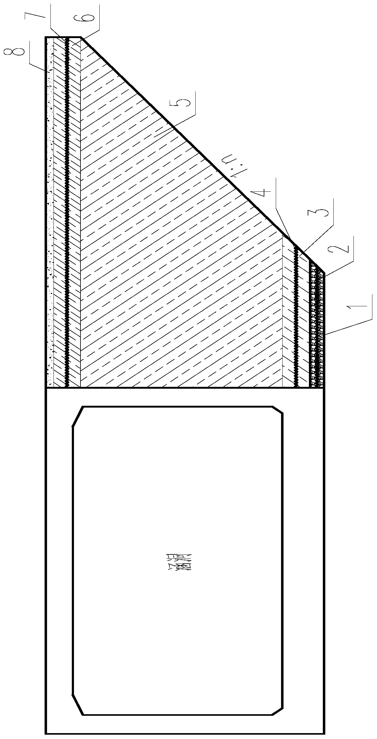
[0030] see figure 1 , the embodiment of the present invention provides a foam lightweight soil subgrade structure for the transition section of the underpass type road culvert, including a sand cushion layer 1, a bottom layer of high-strength foam lightweight soil 3, an ordinary foam lightweight soil 5, and an upper layer of high-strength foam lightweight soil 6 , ordinary concrete 7; a layer of geogrid 2 is laid in the middle of the sand cushion layer 1, a la...


PUM


Abstract

The invention provides an underneath pass type road culvert transition section foam light soil roadbed structure and a construction method thereof. The roadbed structure comprises a sand cushion layerlocated at a bottom of a roadbed, a concrete cushion layer is laid on the sand cushion layer, three parts of foam light soil with different densities are poured on the concrete cushion layer, and a layer of plain concrete is poured on a contact surface of the foam light soil and a ballast bed. Compared with a traditional filler roadbed, the foam light soil roadbed has advantages that self-weightis light and compressive strength is higher; roadbed bearing strength is improved, and a foundation settlement value caused by a generated additional stress is reduced; and rolling vibration is not needed in a construction process, modes of mechanical stirring and pumping pouring operation are adopted, a needed operation area is small, engineering problems that an underneath pass type transition section construction site is limited, large equipment cannot enter a site, and roadbed rolling is not compact can be solved, vertical slope finishing can be achieved, a land acquisition area is reduced, cultivated lands are protected, and construction cost is saved.

Description

technical field [0001] The invention belongs to the field of railway embankment engineering, and in particular relates to a foam light soil embankment structure and a construction method of an underpass type road culvert transition section. Background technique [0002] Due to the development of urban construction, there are more and more crossing projects where new highways pass under existing railway lines, and culverts are widely used in such projects as a structure. When building subgrades on both sides of culverts, the traditional subgrade filling process has the disadvantages that the working surface is narrow, and some construction machinery cannot enter the site for operation; the construction period is long, which affects the normal operation of the line; the degree of subgrade compaction is difficult to control; the gap between the culvert and the subgrade It is easy to have uneven settlement between spaces, resulting in uneven lines and endangering traffic safety ...

Claims


Application Information

Patent Timeline
Patent Type & Authority Applications(China)
IPC IPC(8): E01C3/00E01C3/04E02D3/00E01B2/00
CPCE01B2/00E01C3/00E01C3/04E02D3/005E02D2300/0084
Inventor 刘彬彬龙俊贤余永金张峰曾志姣丁跃凡祝永峰黄俊杰李卫东王广利程先意
Owner CREEC WUHAN SURVEY DESIGN & RES
Why Eureka
Try Eureka