
Bridge simply supported-continuous hogging moment tensioning trolley

A simple support first, then continuous, negative bending moment technology, applied in bridges, bridge construction, erection/assembly of bridges, etc. Numerical control tensioning and other issues, to achieve the effect of numerical control tensioning, simple structure and uniform force

Pending Publication Date: 2020-08-25
GUIZHOU BRIDGE CONSTR GROUP
View PDF0 Cites 8 Cited by
  • Summary
  • Abstract
  • Description
  • Claims
  • Application Information

AI Technical Summary

Problems solved by technology

Due to the limitation of the construction environment, the tension end of the negative moment is located at the lower rafter of the T-beam wing plate, and the special stairs are manually used to go down from the wet joint. Due to the narrow terrain, only one person can operate it. The weight of the jack above 200t exceeds 100kg, and the load There is no supporting platform at the tensioning end of the bending moment, and the whole bundle of tensioning jacks cannot be lifted manually. Therefore, the conventional tensioning system uses a single small jack (commonly known as: bullet jack, weighing about 10kg) for tensioning, so that the working strength will be increased. Disadvantages such as large, not conducive to CNC tensioning, and uneven force on the same bundle of steel hinges

Method used


Image

  • Bridge simply supported-continuous hogging moment tensioning trolley
  • Bridge simply supported-continuous hogging moment tensioning trolley
  • Bridge simply supported-continuous hogging moment tensioning trolley

Examples


Embodiment Construction

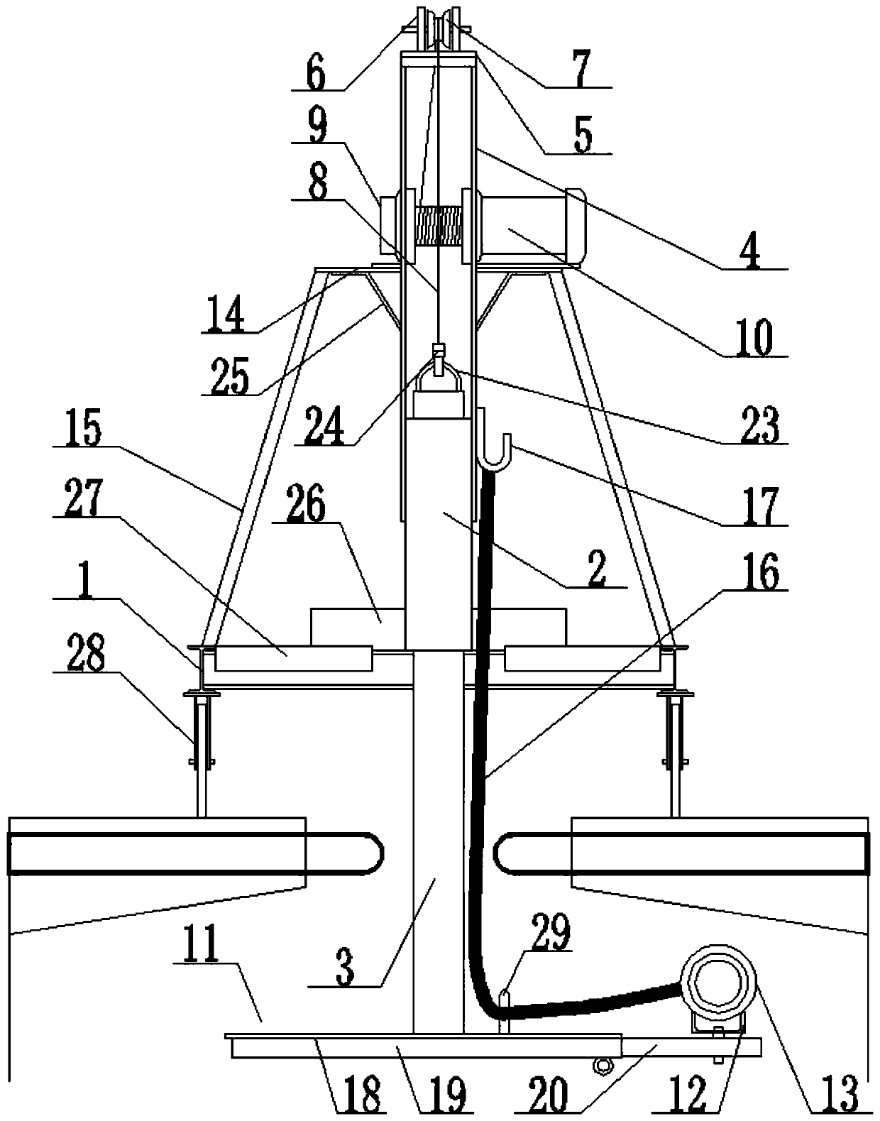
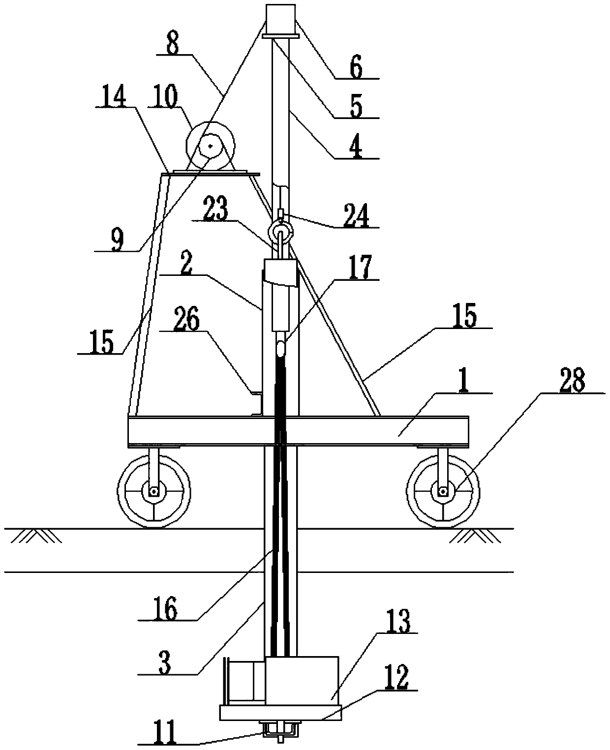
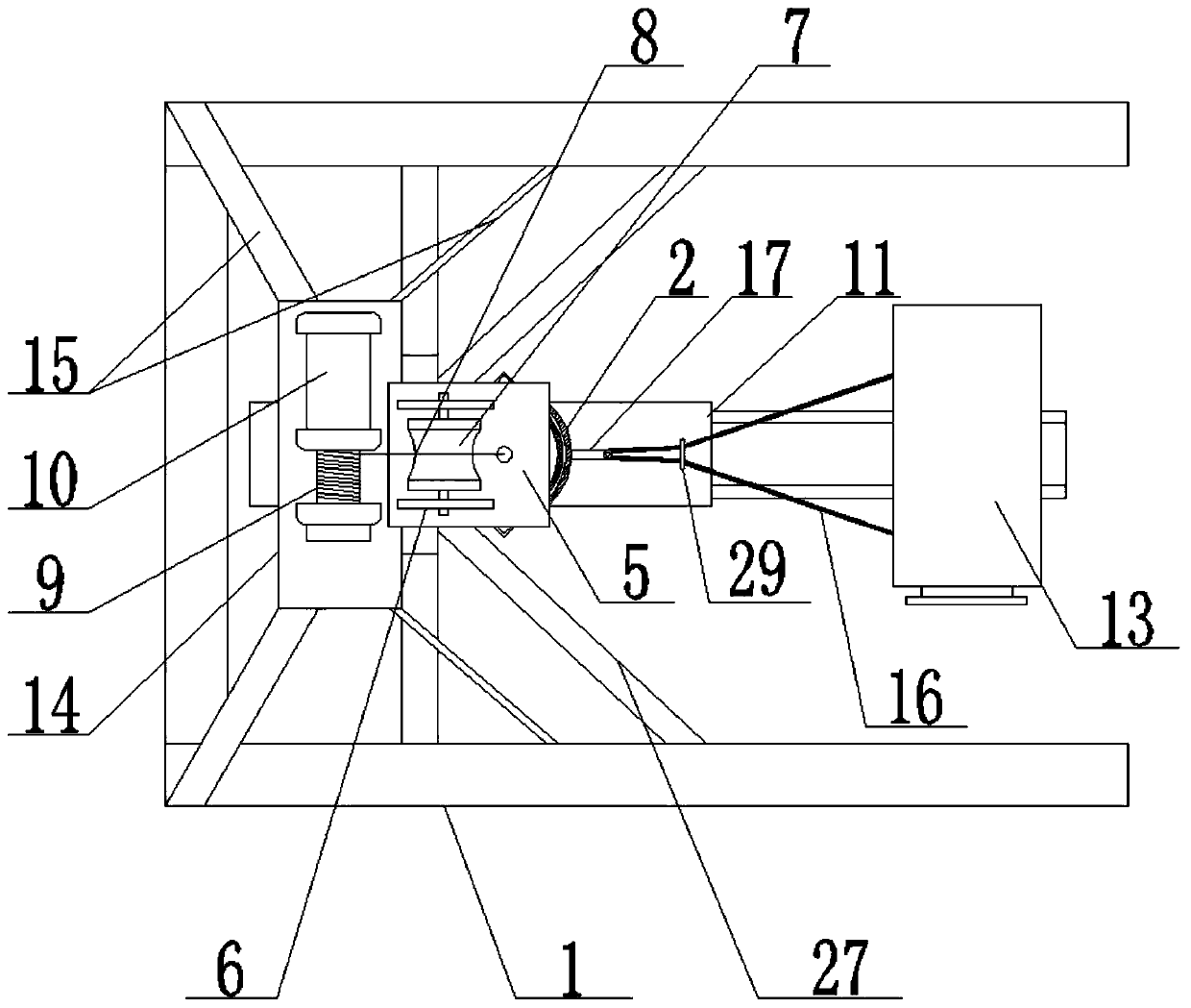
[0021] The present invention will be further described below in conjunction with the accompanying drawings and embodiments, but not as a basis for limiting the present invention.

[0022] Embodiment of the present invention: a bridge is first simply supported and then continuously negative bending moment tensioning trolley, as attached Figure 1-5 As shown, it includes a bottom bracket 1, and the middle position of the bottom bracket 1 is fixed and welded vertically upward with an outer steel pipe 2, and the inner steel pipe 2 is movably penetrated into an inner steel pipe 3. There are two vertically upward angle steels 4 arranged symmetrically on the top, and the tops of the two angle steels 4 are welded to the bottom of the supporting steel plate 5. The surface of the supporting steel plate 5 is fixedly installed with two mounting steel plates 6, and a pulley 7 is arranged between the mounting steel plates 6. , the supporting steel plate 5 below the pulley 7 is provided with...


PUM


Abstract

The invention discloses a bridge simply supported-continuous hogging moment tensioning trolley, which comprises a bottom support; an outer steel pipe is vertically and upwards arranged in the middle of the bottom support; an inner steel pipe penetrates into the outer steel pipe; two vertically upward angle steels are symmetrically arranged on the outer wall of the outer steel pipe; the top ends ofthe two angle steels are connected with the bottom of the supporting steel plate; two mounting steel plates are fixed on the surface of the supporting steel plate; a pulley is arranged between the mounting steel plates; a penetrating hole is formed in the supporting steel plate below the pulley; the steel wire rope is connected with the top of the inner steel pipe after passing through the pulleyand the penetrating hole; the other end of the steel wire rope is connected with a winch; the winch is connected with a motor; the bottom of the inner steel pipe is connected with a sliding rail; andone end of the sliding rail is rotationally connected with a jack mounting plate which is provided with a jack. According to the trolley, the jack is lifted through a rotating and telescopic structure, one-time numerical control tensioning of a whole bundle of steel strands can be achieved, the working intensity is greatly reduced, the stress of the same bundle of steel strands is uniform, and the purpose of numerical control tensioning is achieved.

Description

technical field [0001] The invention relates to a simply supported and then continuously negative bending moment tensioning trolley for a bridge, which belongs to the technical field of bridge construction equipment. Background technique [0002] In order to optimize the stress state of the beam bridge structure, the current beam bridge mostly adopts the structural form of first simply supported and then continuous. The bridge first simply supported and then continuous system relies on negative moment prestress to realize the conversion of the bridge stress system. Negative bending moment prestressing of T-shaped girder bridges is to reserve holes during beam slab prefabrication, make cast-in-place sections at the pier top after erection, and perform prestressed tension on the lower edge of beam slabs. Due to the limitation of the construction environment, the tension end of the negative moment is located at the lower rafter of the T-beam wing plate, and the special stairs a...

Claims


Application Information

Patent Timeline
IPC IPC(8): E01D21/00
CPCE01D21/00
Inventor 代泽森周航方学坤许传平熊伦冯光涛王艺
Owner GUIZHOU BRIDGE CONSTR GROUP
Learn More