Bidirectional reverse circulation continuous deslagging drilling tool

A reverse circulation and drilling tool technology, applied in drill pipes, drill pipes, drill bits, etc., can solve problems such as increasing the resistance of drilling tools, increasing the risk of drilling accidents, and increasing drilling costs, reducing pressure loss and improving Slag discharge capacity and slag discharge stability, the effect of increasing suction negative pressure

Inactive Publication Date: 2020-08-25
CHONGQING UNIV
View PDF6 Cites 1 Cited by
  • Summary
  • Abstract
  • Description
  • Claims
  • Application Information

AI Technical Summary

Problems solved by technology

[0005] The drilling tool of this patent has the following disadvantages: 1. The structure of the drill pipe is complicated, and the reverse circulation hole forming in the process of withdrawing the drill cannot be implemented; 2. The drill hole cannot be repaired when the drill is withdrawn, and the drilling and retreating of the drill hole at any time cannot be realized. , the drilling is unstable and incomplete; 3. The drilling tool needs a casing to protect the hole when drilling, which not only increases the drilling cost, but also increases the risk of drilling accidents in the hole; The spiral groove slag discharge of the drill pipe increases the resistance of the drilling tool during drilling; 5. The drill body is large in size, heavy and inflexible, and is not suitable for construction under underground conditions

Method used


Image

  • Bidirectional reverse circulation continuous deslagging drilling tool
  • Bidirectional reverse circulation continuous deslagging drilling tool
  • Bidirectional reverse circulation continuous deslagging drilling tool

Examples


Embodiment Construction

[0020] Below in conjunction with accompanying drawing and embodiment the present invention will be further described:

[0021] In order to clearly describe the content of the invention, this patent application uses the orientation words "upper" and "lower" to distinguish them. The "upper" and "lower" are determined according to the layout orientation of the above drawings. The name of its location changes accordingly, which cannot be regarded as a limitation on the scope of patent protection.

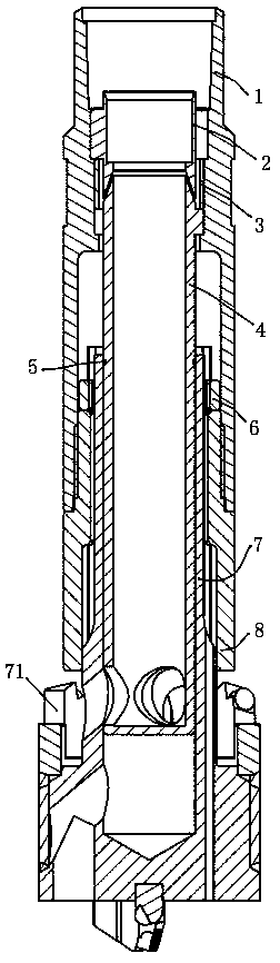
[0022] Such as figure 1 As shown, the present invention includes an outer tube 1, an injection ring 2, a positioning ring 3, a suction core tube 4, a sealing ring 5, a semicircle card 6, a double reverse drill bit body 7 and a spline connection sleeve 8, and the suction core tube 4 Placed inside the outer tube 1, the upper part of the inner wall of the outer tube 1 is provided with a necking step, the radial lugs on the upper part of the suction core tube 4 and the bottom of the positi...


PUM


Abstract

The invention discloses a bidirectional reverse circulation continuous deslagging drilling tool. The bidirectional reverse circulation continuous deslagging drilling tool comprises an outer pipe (1),wherein a suction core pipe (4) is arranged in the outer pipe (1); a radial lug on the upper portion of the suction core pipe (4) and the bottom of a positioning ring (3) are clamped and pressed abovea necking step on the inner wall of the outer pipe; a supporting lug seat of an injection ring (2) is pressed on the top surface of the positioning ring (3); a spline connecting sleeve (8) is in threaded connection with the inner wall of the lower portion of the outer pipe (1); a bidirectional reverse circulation drill bit body (7) is in sliding connection with the spline connecting sleeve (8) through a spline; the lower section of the suction core pipe (4) is inserted into a core hole of the bidirectional reverse circulation drill bit body (7); and a sealing ring (5) is embedded between theouter wall of the suction core pipe (4) and the inner wall of the core hole of the bidirectional reverse circulation drill bit body (7). The bidirectional reverse circulation continuous deslagging drilling tool has the technical effects that the deslagging capability and the deslagging stability of reverse circulation hole forming are improved, during drill withdrawing, a hole wall is trimmed, collapsed coal slag is also discharged, and drilling accidents such as drill locking and hole spraying caused by accumulation of a large amount of coal slag in a drill hole of a soft coal seam are avoided.

Description

technical field [0001] The invention belongs to the technical field of drilling, and in particular relates to a drilling tool for continuous slag discharge and hole forming with double reverse circulation. Background technique [0002] In this patent application, double reverse circulation is two-way reverse circulation: reverse circulation is used to form holes when drilling in the forward direction, and reverse circulation is still used to form holes when drilling in the reverse direction. Reverse circulation hole formation refers to the hole formation in which the driving fluid enters the hole from the annular gap between the drill tool and the hole wall when drilling, carries the drilling slag, and then discharges out of the hole through the center channel of the drill tool. [0003] Due to the low strength, poor permeability and high gas content of soft coal seams in coal mines, dynamic disasters such as collapse, injection holes, and drill holes often occur in gas drai...

Claims


Application Information

Patent Timeline
Patent Type & Authority Applications(China)
IPC IPC(8): E21B17/18E21B21/16E21B21/12E21B10/42E21B10/60
CPCE21B10/42E21B10/602E21B17/18E21B21/12E21B21/16
Inventor 何将福罗永江李莉佳孙宵一荣健淇吴哲理江东晓
Owner CHONGQING UNIV
Why Eureka
Try Eureka