Tower type heat absorber and operation method
A heat absorber and tower-type technology, which is applied in the design field of tower-type solar heat absorbers, can solve problems affecting the normal operation of the heat absorber, shortening the service life of the heat absorber, uneven heating of the heat absorbing tubes, etc., and reaches the difficulty of manufacturing technology Low, reduce light rejection rate, low cost effect
- Summary
- Abstract
- Description
- Claims
- Application Information
AI Technical Summary
Problems solved by technology
Method used
Image
Examples
Embodiment 1
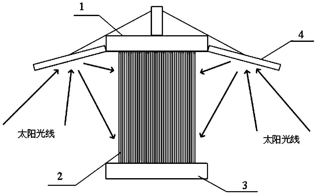
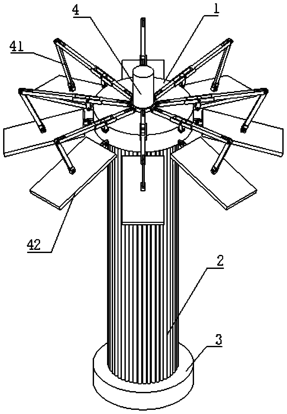
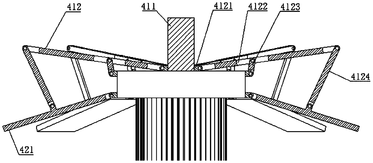
[0062] see Figure 1-5 , the tower heat absorber of the present embodiment comprises an upper header 1, a lower header 3 and a heat-absorbing pipe assembly 2 arranged between the upper header 1 and the lower header 3, and the upper end of the upper header is provided with Sunlight secondary reflection device 4, the heat-absorbing pipe assembly 2 is a heat-absorbing screen formed by a plurality of heat-absorbing pipes 21, and the connection between the heat-absorbing pipe assembly 2 and the upper header 1 and the lower header 3 is close to the upper Collecting box 1, lower collecting box 3 periphery; Described solar ray secondary reflection device 4 comprises posture adjustment device 41 and reflection plate group 42, and described posture adjustment device 41 comprises frame 411 and reflection plate angle adjustment assembly 412, described The reflector group 42 includes reflectors 421 uniformly distributed in an umbrella shape along the circumferential direction of the upper ...
Embodiment 2
[0075] The difference with said embodiment 1 is: see Figure 6-9 , the attitude adjustment device 41 is a rope drive, the frame 411 is a hollow structure, and the reel 4125 is fixedly connected with the upper end surface of the upper header 1 inside, and the middle part of the upper end surface of the frame 411 is provided with a branching hole 4111, the upper end surface is distributed along the circumferential direction with the distribution slideway 4126. Correspondingly, the outer circumference of the upper end of the upper header 1 is provided with a driving rope limit ring 4128. One end of the driving rope 4127 is wound on the reel 4125, and the output end is divided into multiple Branches, each branch passes through the corresponding branching hole 4111, branching slideway 4126 and driving rope limit ring 4128 in turn, and the end is fixedly connected with the back of the reflection plate 421.
[0076] The hinge joint between the inner edge of the reflection plate 421 a...
Embodiment 3
[0081] The difference from the second embodiment is that: the hinge joint between the inner edge of the reflection plate 421 and the outer circumference of the upper header 1 is a spring hinge.
[0082] The advantage of this embodiment is that compared with multi-gear self-locking hinges, the inclination angle of the reflection plate 421 is not limited by the gear position, and the inclination angle of the reflection plate 421 can be infinitely adjusted.
PUM
 Abstract
Description
Claims
Application Information
 - R&D
- Intellectual Property
- Life Sciences
- Materials
- Tech Scout
- Unparalleled Data Quality
- Higher Quality Content
- 60% Fewer Hallucinations
Browse by: Latest US Patents, China's latest patents, Technical Efficacy Thesaurus, Application Domain, Technology Topic, Popular Technical Reports.
© 2025 PatSnap. All rights reserved.Legal|Privacy policy|Modern Slavery Act Transparency Statement|Sitemap|About US| Contact US: help@patsnap.com


