Eureka AIR delivers breakthrough ideas for toughest innovation challenges, trusted by R&D personnel around the world.

Refrigerator

A refrigerator and sealing cavity technology, applied in the field of home appliances, can solve problems such as long control lines, and achieve the effects of good heat absorption, cost reduction, and slow flow rate

Inactive Publication Date: 2020-08-25
合肥仙湖半导体科技有限公司
View PDF5 Cites 0 Cited by
  • Summary
  • Abstract
  • Description
  • Claims
  • Application Information

AI Technical Summary

Problems solved by technology

[0004] In order to solve the technical problem of the existing refrigerator that the control board is located on the top of the refrigerator, the control line between the control board and the compressor at the bottom of the refrigerator is too long, the present invention provides a refrigerator

Method used


Image

  • Refrigerator
  • Refrigerator
  • Refrigerator

Examples


Embodiment 1

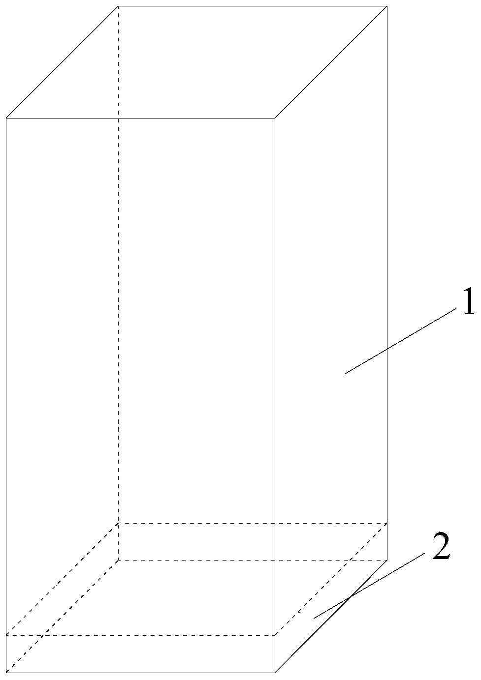
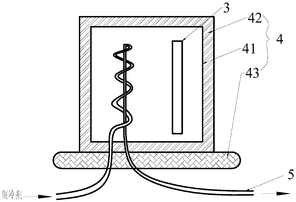
[0036] see figure 1 and figure 2 , The refrigerator of this embodiment includes a casing 1, a compressor (not shown), a control panel 3, and an installation structure 4.

[0037] Various electronic devices are installed on the control panel 3, and these electronic devices are mainly used to form a control system for controlling the operation of the refrigerator, such as controlling the operation of the compressor.

[0038] The bottom of casing 1 is provided with compressor cabin 2, and compressor, control board 3, installation structure 4 are all installed in compressor cabin 2. The temperature in the compressor compartment 2 is relatively high due to the operation of the compressor, often higher than 50°C, which exceeds the ambient temperature requirements of each electronic device on the control board 3.

[0039] The present invention enables the control panel 3 to be installed in the compressor compartment 2 by designing the installation structure 4 , thereby changing th...

Embodiment 2

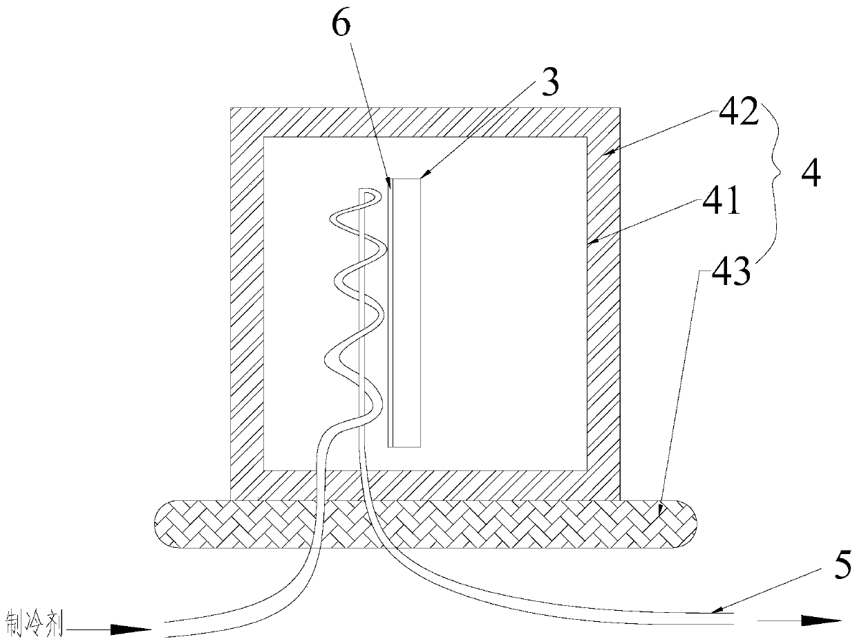
[0049] see image 3 The difference between this embodiment and Embodiment 1 is that: the side of the control board 3 facing the return pipe 5 is provided with a thermally conductive insulating layer 6, such as a high thermally conductive insulating layer made of high thermally conductive insulating composite powder. The main components of high thermal conductivity insulating composite powder are nano-silicon magnesium nitride, nano-silicon carbide, nano-aluminum nitride, nano-boron nitride, high-sphericity alumina, nano-silicon nitride (regular orientation structure), etc. The combination of fillers, according to the particle size, shape, surface wettability, doping fraction, and thermal conductivity of each material, use particles with different particle sizes to form the largest packing degree between the fillers and make the system The heat conduction network in it is formed to the greatest extent to achieve effective heat conduction and obtain a high heat conduction system...

Embodiment 3

[0052] The difference between this embodiment and Embodiment 1 is that the spiral structure is positioned in the sealed cavity 41 through a metal heat conducting sheet. Thereby, the present invention is easier to realize, plays a better positioning effect on the spiral structure, and the installation in the sealed cavity 41 is also more convenient and free. The metal heat conducting sheet can be a rectangular sheet parallel to the control board 3.


PUM


Abstract

The invention discloses a refrigerator. The refrigerator comprises a box body, a compressor, a control panel and a mounting structure. The mounting structure comprises a sealing cavity provided with the control panel, a heat insulation layer wrapped outside the sealing cavity and a plastic fixed part fixedly coated with the sealing cavity of the heat insulation layer. A trace of a return pipe penetrating into the sealing cavity is of a spiral structure, is turned to a vortex of the spiral structure on the top and extends outside the sealing cavity from the vortex. The spiral extension direction of the spiral structure is parallel to the control panel, and a heat conducting insulation layer is arranged on the side, facing the spiral structure, of the control panel. Compared with a conventional refrigerator, the control panel is transferred from the top of the refrigerator to a compressor cabin at the bottom of the refrigerator, so that the line cost is lowered; the control panel is cooled by means of cold air in the return pipe on the compressor cabin; the cooled control panel and the compressor cabin are independent fully; and a condensation phenomenon due to condensation of pipe wall of the return pipe can be prevented.

Description

technical field [0001] The invention relates to a refrigerator in the field of household appliances. Background technique [0002] A refrigerator is an appliance that maintains low temperatures by keeping food or other items in a constant cold state to avoid spoilage. In ancient refrigerators, tin was hung inside, and there was a small hole in the bottom of the box. One of the two cover plates was fixed on the mouth of the box, and the other was a trap into which ice cubes were placed to keep the temperature in the box low. There are compressors, ice machines, cabinets or boxes for freezing in the cabinets of modern refrigerators, and storage boxes with refrigeration devices. [0003] The compressor is installed in the compressor compartment of the refrigerator, and generally the compressor compartment is located at the bottom of the refrigerator. Although there is enough space in the compressor compartment to place the control panel of the refrigerator, due to the relativ...

Claims


Application Information

Patent Timeline
IPC IPC(8): F25D11/00F25D17/04F25D19/00F25D21/04F25D29/00
CPCF25D11/00F25D17/04F25D19/00F25D21/04F25D29/003F25D29/005Y02B40/00
Inventor 黄明乐
Owner 合肥仙湖半导体科技有限公司
Why Eureka
Eureka Blog
Learn More