Method and device for testing nonlinear effect I * L value of optical element

A technology of nonlinear effects and optical components, applied in the field of optical detection, can solve problems such as scattered laser loss, achieve the effects of improving test accuracy, improving small-scale self-focusing filament damage threshold, and high applicability

Active Publication Date: 2020-08-25
中国工程物理研究院上海激光等离子体研究所
View PDF7 Cites 4 Cited by
  • Summary
  • Abstract
  • Description
  • Claims
  • Application Information

AI Technical Summary

Problems solved by technology

[0005] In view of this, the present invention provides a method and device for testing the nonlinear effect I*L value of an optical element. By adopting the method of focusing the laser beam in the optical element body, the disturbance-induced small-scale self-improvement under non-focusing conditions is simulated. The focus effect solves the problem of laser loss such as scattering and defect absorption caused by the damage of the incident surface of the optical element in the traditional test method because the damage of the incident surface of the optical element occurs before the self-focusing filament damage in the body, which not only improves the test accuracy , and also provide more help for the safe use of optical components in high-power laser devices and to improve the ability of materials to resist laser damage

Method used


Image

  • Method and device for testing nonlinear effect I * L value of optical element
  • Method and device for testing nonlinear effect I * L value of optical element
  • Method and device for testing nonlinear effect I * L value of optical element

Examples


Embodiment Construction

[0052] In order to better understand the technical solutions of the present invention, the embodiments of the present invention will be described in detail below in conjunction with the accompanying drawings.

[0053] It should be clear that the described embodiments are only some of the embodiments of the present invention, not all of them. Based on the embodiments of the present invention, all other embodiments obtained by persons of ordinary skill in the art without creative efforts fall within the protection scope of the present invention.

[0054] The present application will be described in further detail below through specific embodiments and in conjunction with the accompanying drawings.

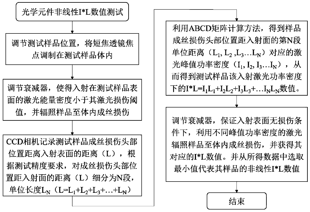
[0055] The invention provides a method and device for testing the nonlinear effect I*L value of an optical element. The I*L value is one of the important indicators for evaluating the nonlinear effect of nonlinear crystals. This test method focuses the laser beam in the body of the...


PUM

PropertyMeasurementUnit
wavelengthaaaaaaaaaa

Abstract

The invention discloses a method and a device for testing a nonlinear effect I * L value of an optical element. According to the method, a laser beam is focused in an optical element body by using a lens of which the focal length is smaller than the thickness of the optical element and adjusting the position of the optical element; meanwhile, the laser energy density of laser irradiation on the incident plane of the optical element to be measured is adjusted to be smaller than the laser damage threshold value of the incident plane of the optical element to be measured; a disturbance-induced small-scale self-focusing effect under a non-focusing condition is simulated; in a traditional test method, an incident surface of an optical element is damaged before in-vivo self-focusing filamentation; therefore, the problems of scattering, defect absorption and other laser losses caused by the damage of the incident surface of the optical element are solved, the test precision is improved, and more help is provided for the safe use of the optical element in a high-power laser device and the improvement of the laser damage resistance of the material.

Description

technical field [0001] The invention relates to the technical field of optical detection, in particular to a method and device for testing the nonlinear effect I*L value of an optical element. Background technique [0002] In laser inertial confinement fusion, the filamentary damage of optical elements caused by the nonlinear small-scale self-focusing effect has become a bottleneck problem that limits the laser output power and increases the risk and cost of device operation. The small-scale self-focusing effect is due to the local instability of the beam caused by the phase and amplitude modulation of the laser during transmission in the nonlinear medium, which splits the beam into high-intensity filaments to induce material damage. The I*L value of a nonlinear medium is one of the important bases for evaluating its small-scale self-focusing effect. I is the peak power density of the incident laser, and L is the distance from the initiation point of filamentation damage to ...

Claims


Application Information

Patent Timeline
Patent Type & Authority Applications(China)
IPC IPC(8): G01M11/02
CPCG01M11/0242G01M11/0278
Inventor 单翀赵晓晖高妍琦崔勇季来林李小莉饶大幸刘栋夏兰郑权赵元安刘晓凤朱翔宇
Owner 中国工程物理研究院上海激光等离子体研究所
Why Eureka
Try Eureka