Blooming down-the-hole pattern design method used on continuous rolling mill

A design method and continuous rolling mill technology, applied in design optimization/simulation, roll, metal rolling, etc., can solve problems such as low roll body utilization, long roll body length, and large pass outer width, etc., to achieve Reduced roll weight, improved utilization, and reduced roll diameter

Active Publication Date: 2020-08-25
建龙北满特殊钢有限责任公司
View PDF12 Cites 0 Cited by
  • Summary
  • Abstract
  • Description
  • Claims
  • Application Information

AI Technical Summary

Problems solved by technology

[0006] (2) The utilization rate of the roll body is low
[0007] Due to the deep groove of the box-type pass, when the slope of the side wall of the pass is fixed, the width of the outer opening of the pass is large. When the pass is arranged, the length of the roll body is occupied. low rate
[0008] (3) The roll is heavy
[0009] Due to the deep groove of the box-shaped pass, the difference between the roll body diameter and the working diameter of the roll is large. Therefore, under the premise of ensuring the working diameter of the roll, the roll body diameter of the roll is also relatively large, which increases the weight of the roll.

Method used


Image

  • Blooming down-the-hole pattern design method used on continuous rolling mill
  • Blooming down-the-hole pattern design method used on continuous rolling mill
  • Blooming down-the-hole pattern design method used on continuous rolling mill

Examples


Embodiment Construction

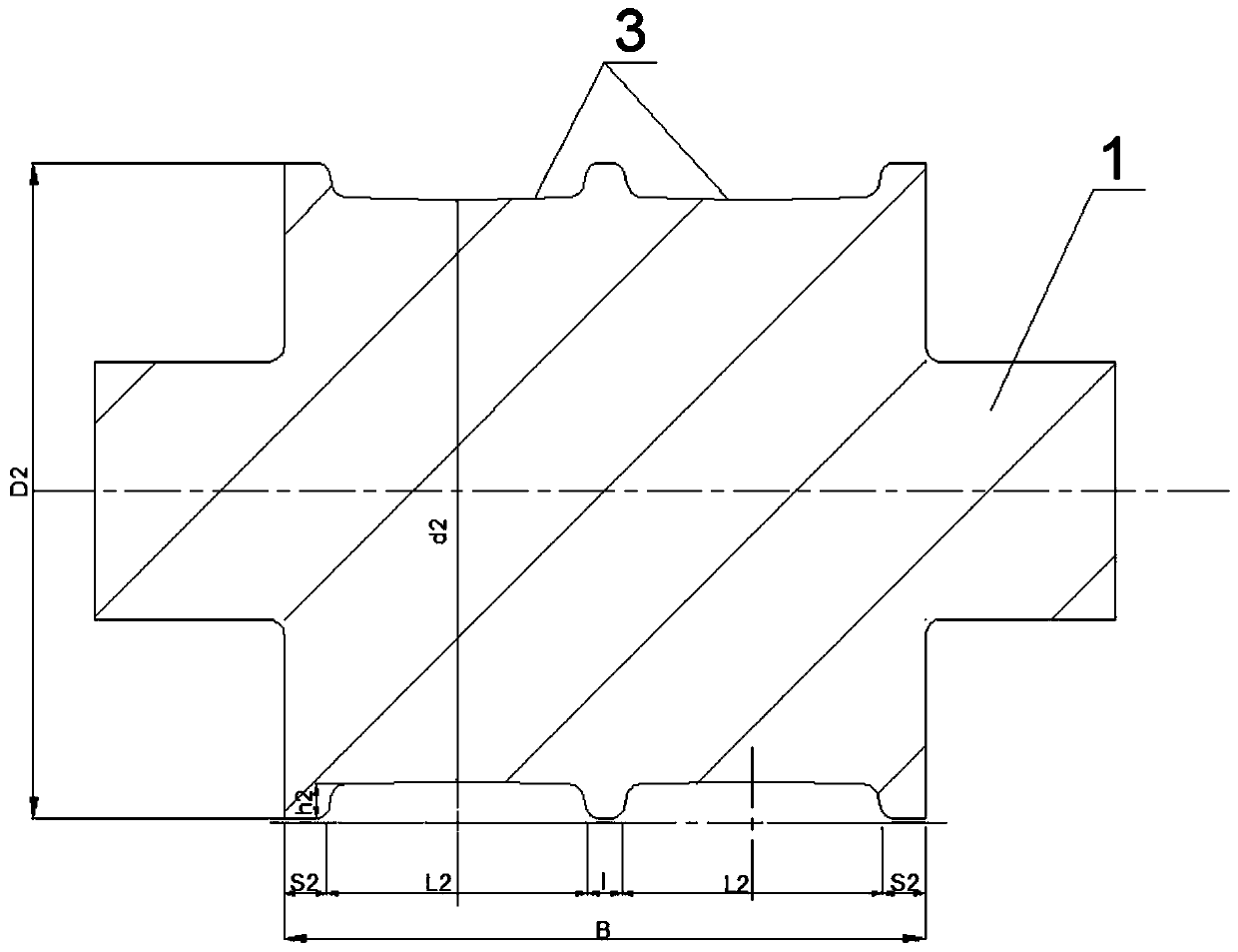
[0037] Such as figure 1 with Figure 5 As shown, the present invention is a design method for the blooming submerged pass type used on the continuous rolling mill. A box-shaped pass type is processed on the surface of the roll 1, and the side wall of the pass type is inclined, and specifically includes The following steps:

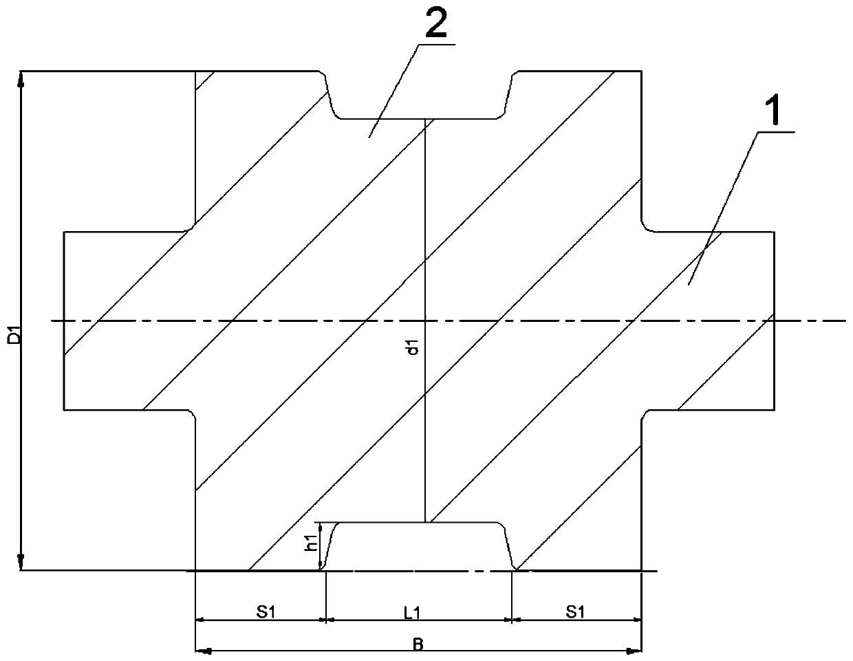
[0038] Step 1: According to the groove depth of the existing hole type 2, the groove depth of the submerged hole type 3 is determined by the following formula. The slope of the side wall of the submerged hole type 3 is the same as that of the existing hole type 2, namely :

[0039] h 2 = 1 / 2h 1

[0040] Where: h 2 is the groove depth of down-the-hole type, h 1 Notch depth for existing pass pattern

[0041] Due to the reduced groove depth of DTH type 3, the roll body diameter D 2 and roll working diameter d 2 The difference is reduced by half compared with the original design, so that the groove bottom of submerged hole type 3 is located at a high...


PUM

PropertyMeasurementUnit
diameteraaaaaaaaaa

Abstract

The invention discloses a blooming down-the-hole pattern design method used on a continuous rolling mill, belongs to the technical field of steel rolling, and aims at the current situation that the utilization rate of an existing roller body is low, and the blooming down-the-hole pattern design method comprises the specific steps that under the condition that the inclination of the side wall of anexisting hole pattern is not changed, the grooving depth of the existing hole pattern is reduced; according to the grooving depth of the down-the-hole patterns and the number of the down-the-hole patterns, the roll collar width of the edge of the roll is obtained; the number of the down-the-hole patterns distributed on the roller needs to meet the requirement that S is larger than or equal to h;and under the condition that the working diameters of the rollers are the same, the diameters of the rollers are determined according to the grooving depth of the down-the-hole pattern. On the premisethat the rolling quality of special steel products is guaranteed, an existing hole pattern is designed into a down-the-hole pattern, the grooving depth of the hole pattern on the roller is reduced byhalf, then the groove bottom of the hole pattern is located at the position with a high hardness layer, the requirement for the steel passing amount of the roller is met, and the use cost of the roller is reduced.

Description

Technical field: [0001] The invention belongs to the technical field of steel rolling, and in particular relates to a design method of a submerged hole profile for blooming used in a continuous rolling mill. Background technique: [0002] In the field of rolled steel and long product production, in order to reduce the consumption of rolls, various production enterprises have used many innovative methods in pass design. The typical one is to use flat roll without pass rolling to replace the box-type rolling of the continuous rolling mill. —Ellipse-circle pass system rolling effectively reduces the steel consumption per ton of rolls. However, since flat roll non-perforated rolling forms sharp corners during the deformation process, it is easy to form surface folding defects in the subsequent transition to a round process. It is used for building materials that do not require high surface quality, and is not suitable for the production of special steel products. In the use of...

Claims


Application Information

Patent Timeline
Patent Type & Authority Applications(China)
IPC IPC(8): G06F30/17G06F30/20G06F17/10B21B27/02G06F111/10
CPCG06F30/17G06F30/20G06F17/10B21B27/02G06F2111/10Y02P70/10
Inventor 陈金富满春红
Owner 建龙北满特殊钢有限责任公司
Why Eureka
Try Eureka