A Radar/IR Compatible Stealth Metasurface

A metasurface, infrared technology, applied in antennas, electrical components, etc., can solve the problems of complex structure and poor performance of radar and infrared compatible stealth materials, achieve good radar and infrared compatible stealth performance, suppress grating lobe effect, and optimize bandwidth. The effect of thickness ratio

Active Publication Date: 2021-08-06
XI AN JIAOTONG UNIV
View PDF6 Cites 0 Cited by
  • Summary
  • Abstract
  • Description
  • Claims
  • Application Information

AI Technical Summary

Problems solved by technology

[0003] In order to solve the problem of complex structure and poor performance of radar and infrared compatible stealth materials in the prior art, the present invention provides a radar / infrared compatible stealth metasurface, the radar / infrared compatible stealth metasurface is composed of a conductive reflective layer-dielectric layer- Conductor thin film functional layer sandwich structure, simple structure, only one layer of artificial structure unit array can make the above structure realize the compatibility of radar and infrared stealth at the same time

Method used


Image

  • A Radar/IR Compatible Stealth Metasurface
  • A Radar/IR Compatible Stealth Metasurface
  • A Radar/IR Compatible Stealth Metasurface

Examples


Embodiment 1

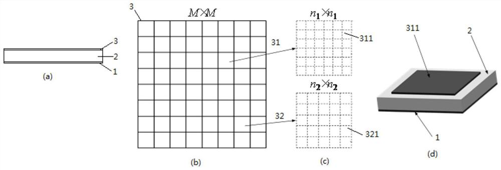
[0039] A radar / infrared compatible stealth metasurface, starting from the conductive metal copper reflective layer 1, from bottom to top, including FR4 dielectric layer 2 and conductive thin film functional layer 3, the thickness of the conductive metal copper reflective layer 1 is 0.02mm, and the FR4 dielectric layer The thickness is 1.5mm, the real part of the relative permittivity is 10, the loss tangent value is 0.2, and the functional layer of the conductor film is a metal copper film. The large unit II32 is arranged in a 6×6 array structure according to the checkerboard structure; the large patch unit I31 is arranged in a 26×26 structure by the small patch unit I311 with a size of 1.05mm, and the large patch unit II32 is composed of small patch units with a size of 2.97mm The small patch unit II321 is arranged in a 10×10 structure, the thickness of the patch small unit I311 and the patch small unit II321 are both 0.02mm, the gap between two adjacent patch small units I311...

Embodiment 2

[0042]A radar / infrared compatible stealth metasurface, starting from the conductive metal copper reflective layer 1, from bottom to top, including FR4 dielectric layer 2 and conductive thin film functional layer 3, the thickness of the conductive metal copper reflective layer 1 is 0.02mm, and the FR4 dielectric layer The thickness is 3.8mm, the real part of the relative permittivity is 5, the loss tangent value is 0.001, and the functional layer of the conductor film is a metal copper film. The large unit II32 is arranged in a 6×6 array structure according to the checkerboard structure; the large patch unit I31 is arranged in a 56×56 structure by the small patch unit I311 with a size of 0.7mm, and the large patch unit II32 is composed of small patch units with a size of 6.3mm The small patch unit II321 is arranged in an 8×8 structure, the thickness of the patch small unit I311 and the patch small unit II321 are both 0.02mm, the gap between the adjacent patch small units I311, t...


PUM

PropertyMeasurementUnit
thicknessaaaaaaaaaa
thicknessaaaaaaaaaa
thicknessaaaaaaaaaa

Abstract

The invention discloses a radar / infrared compatible stealth supersurface, which belongs to the technical field of new artificial electromagnetic materials, and comprises a conductive reflection layer, a dielectric layer and a conductive thin film functional layer arranged sequentially from bottom to top; the conductive thin film functional layer is a paste The M×M array structure of the large patch unit I and the large patch unit II; the large patch unit I is composed of small patch units I 1 ×n 1 array structure, the patch large unit II is composed of patch small unit II n 2 ×n 2 wherein, M is an even number; the large patch unit I and the large patch unit II have the same size and equal number; the small patch unit I and the small patch unit II have different sizes; the present invention consists of a conductive reflective layer-medium Layer-Conductor thin film functional layer sandwich structure, simple structure, only one layer of artificial structure unit array can make the above structure realize the compatibility of radar and infrared stealth at the same time.

Description

technical field [0001] The invention belongs to the technical field of novel artificial electromagnetic materials, and in particular relates to a radar / infrared compatible stealth metasurface. Background technique [0002] Absorbing material is one of the main technical approaches to realize radar stealth, but it reduces radar echo through electromagnetic wave absorption, which is in contradiction with the infrared low emission stealth mechanism. Therefore, realizing radar and infrared compatible stealth has always been the focus of attention in the field of stealth technology. The traditional method is to spray a layer of infrared low-emissivity coating on the surface of the absorbing material, but this often leads to the decline of radar absorbing performance. With the development of new artificial electromagnetic materials, the deficiencies of traditional technologies can be better solved through the designability and frequency selection characteristics of artificial stru...

Claims


Application Information

Patent Timeline
Patent Type & Authority Patents(China)
IPC IPC(8): H01Q17/00H01Q15/00
CPCH01Q15/0086H01Q17/008
Inventor 庞永强屈冰玥夏颂徐卓
Owner XI AN JIAOTONG UNIV
Why Eureka
Try Eureka