Tire bead cutting and wire stripping device and method

A bead and cutting technology, applied in the field of waste tires, can solve the problems of low efficiency, high labor cost, no wire stripping system, etc., and achieve the effect of improving the degree of stripping, improving the effect of stripping, and saving manpower and material resources.

Pending Publication Date: 2020-08-28
SAILUN GRP CO LTD +1
View PDF0 Cites 2 Cited by
  • Summary
  • Abstract
  • Description
  • Claims
  • Application Information

AI Technical Summary

Problems solved by technology

There are still a large number of recycled materials in waste tires, such as metal materials such as wire rings in the bead and steel belts in the belt layer. At this stage, there is no relatively complete waste tire treatment method, and there is no complete waste tire Most of the tires are destroyed in the directional processing system of each half part, and the utilization rate of waste materials is low, which greatly causes waste of materials
At present, there are some crude devices for bead stripping, but they are all manually operated, and the manual operation accuracy is low, the labor cost is high, and there is a certain risk of operation; the continuity of tire processing is poor, and only Separate bead wire stripping is inefficient and cannot meet the requirements of working conditions when dealing with a large number of waste tires
There is also no complete stripping system for tire beads, which hinders the industrialization and automation of waste tires

Method used


Image

  • Tire bead cutting and wire stripping device and method
  • Tire bead cutting and wire stripping device and method
  • Tire bead cutting and wire stripping device and method

Examples


Embodiment Construction

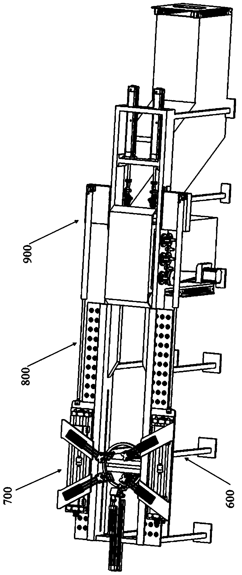
[0042] Such as figure 1 As shown, a bead cutting and stripping device, including

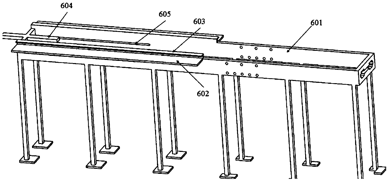
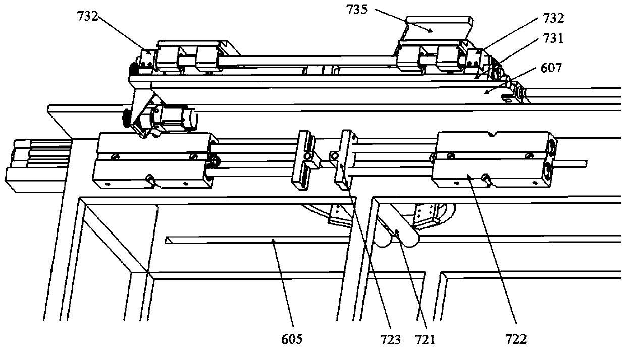
[0043] Workbench mechanism 600, described workbench mechanism comprises workbench body 601, the workbench lower plate 602 that is arranged on the workbench body and the workbench top plate 603, the workbench cross seat that is arranged on the workbench body one end 604, and the workbench slideway 605 that is set on the both side walls of the workbench body, the multi-row bull's-eye wheel 606 that is installed on the workbench lower plate and the workbench upper plate, is arranged on the workbench upper plate and the lower plate. The first layer board 607 that can reciprocate along the bull's-eye wheel between the boards and the layer board cylinder 608 that drives the movement of the first layer board; the first layer board is provided with a horizontally moving slide rail assembly.

[0044] The bead cutting mechanism 700 includes a cutter assembly 710 installed at the end of the workbench mech...


PUM


Abstract

The invention relates to a tire bead cutting and wire stripping device and method. The device comprises a workbench mechanism, a tire bead cutting mechanism, a tire bead hauling mechanism and a tire bead wire stripping mechanism; the tire bead cutting mechanism comprises a cutting tool assembly installed at the end part of the workbench mechanism, a moving roller assembly with adjustable clearanceinstalled on the workbench, horizontal moving slide rail assemblies installed on two sides of the workbench mechanism, and clamping assemblies installed on the horizontal moving slide rail assemblies; the tire bead hauling mechanism is installed on the workbench mechanism and positioned at the rear side of the tire bead cutting mechanism, and is used for transporting a cut tire bead to the tire bead wire stripping mechanism; and the tire bead wire stripping mechanism is installed on the workbench mechanism, and comprises a tire bead wire stripping assembly, a debris storage box positioned right below the tire bead wire stripping assembly, a steel wire hauling assembly positioned on the rear side of the tire bead wire stripping assembly, and a steel wire storage box positioned below the steel wire hauling assembly. The tire bead cutting and wire stripping device and method has the beneficial effects that, cutting and wire stripping operation of the tire bead can be completed, the degree of automation is high, the level of mechanism linkage and integration is high, and operation ability of a system is improved.

Description

technical field [0001] The invention belongs to the technical field of waste tires, in particular to a bead cutting and stripping device and method. Background technique [0002] With more and more waste tires being scrapped, more and more people pay more and more attention to the secondary utilization of waste tire materials. There are still a large number of recycled materials in waste tires, such as metal materials such as wire rings in the bead and steel belts in the belt layer. At this stage, there is no relatively complete waste tire treatment method, and there is no complete waste tire Most of the tires are destroyed in the directional processing system of each half part, and the utilization rate of waste materials is low, which greatly causes waste of materials. At present, there are some crude devices for bead stripping, but they are all manually operated, and the manual operation accuracy is low, the labor cost is high, and there is a certain risk of operation; th...

Claims


Application Information

Patent Timeline
Patent Type & Authority Applications(China)
IPC IPC(8): B29B17/02B29B17/04B02C4/08B02C4/42B26D7/02B26D1/18B26D5/08B26D5/04
CPCB02C4/08B02C4/42B02C2201/04B26D1/18B26D5/04B26D5/086B26D7/02B29B17/02B29B17/04B29B2017/0268B29B2017/0476Y02W30/62
Inventor 尹广俊高明吕龙冯希金周天明李文文张克林
Owner SAILUN GRP CO LTD
Why Eureka
Try Eureka