Desktop-level 3D printing equipment

A 3D printing, desktop-level technology, applied in the field of 3D printing, can solve the problems of narrow use range of parts, low degree of automation, poor printing effect, etc., and achieve the advantages of easy motion control precision detection, high space utilization, and reduced energy consumption Effect

Active Publication Date: 2020-08-28
哈尔滨自由智造科技开发有限公司
View PDF11 Cites 0 Cited by
  • Summary
  • Abstract
  • Description
  • Claims
  • Application Information

AI Technical Summary

Problems solved by technology

[0005] The present invention aims to solve the problems that existing miniaturized 3D printing equipment has relatively single materials, resulting in narrow use range of parts, low degree of au...

Method used


Image

  • Desktop-level 3D printing equipment
  • Desktop-level 3D printing equipment
  • Desktop-level 3D printing equipment

Examples


specific Embodiment approach 1

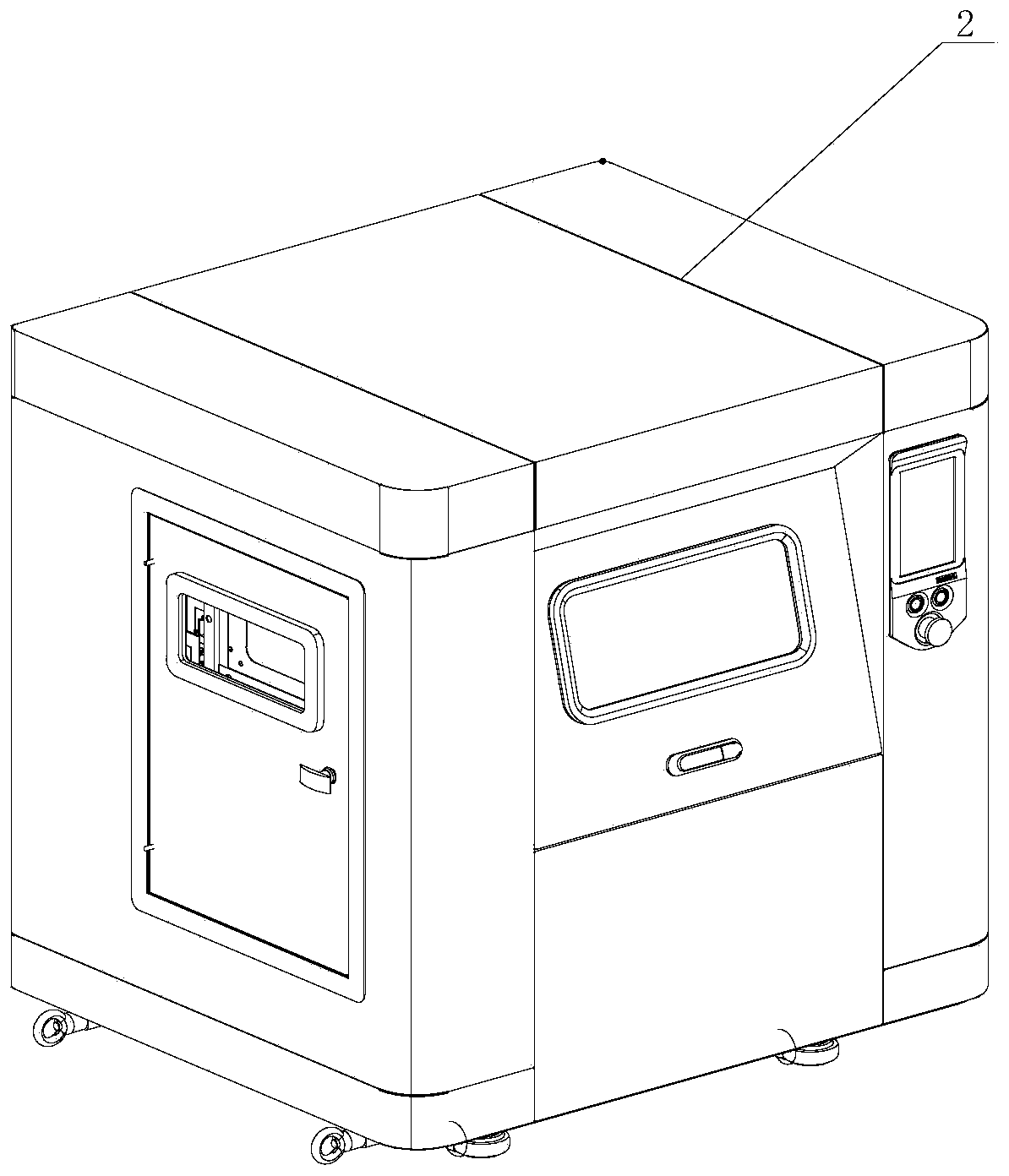
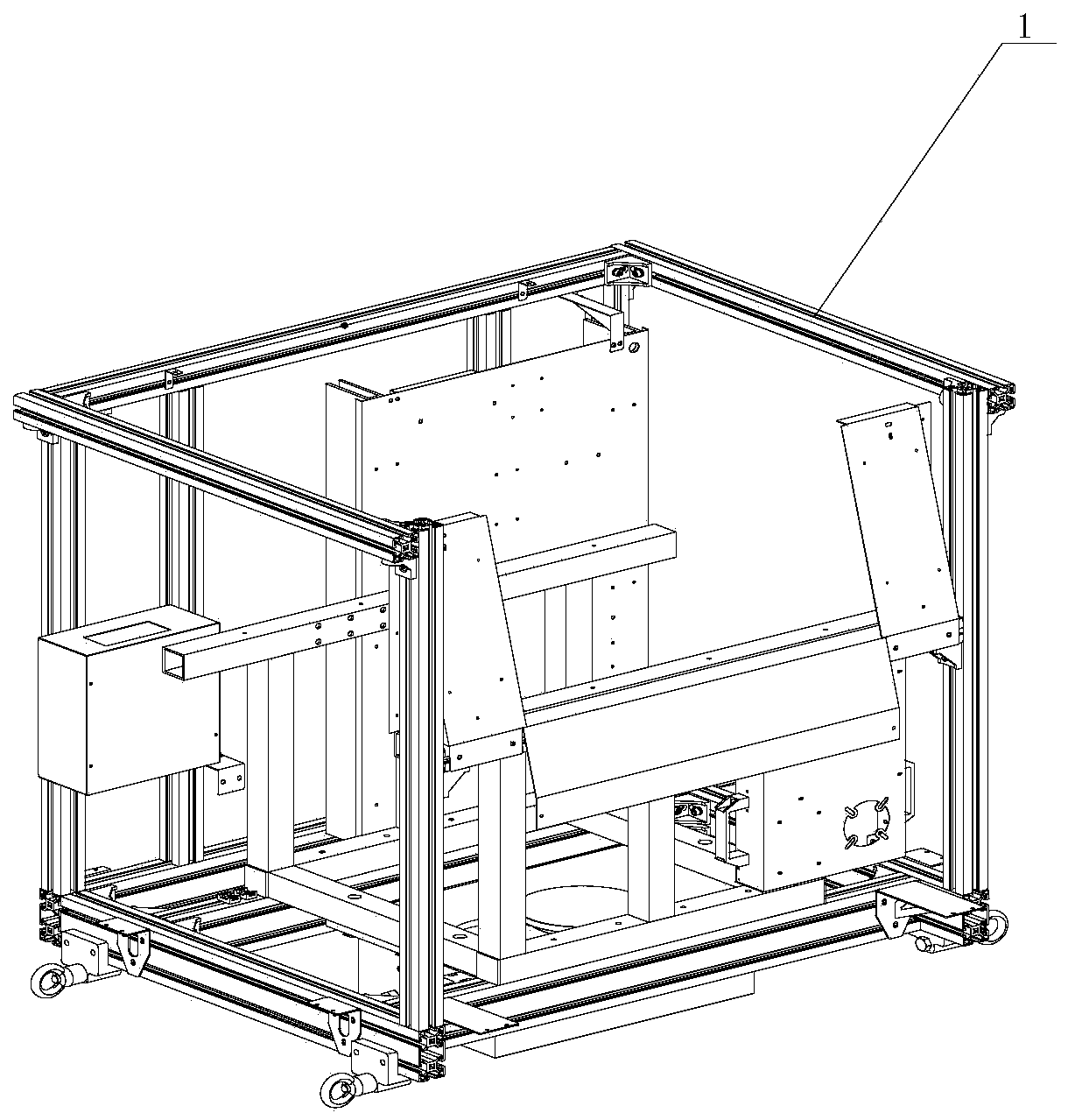
[0036] Specific implementation mode one: combine Figure 1 to Figure 3 Describe this embodiment, a desktop 3D printing device described in this embodiment includes a frame 1 and a casing 2, and the casing 2 is set on the frame 1; the desktop 3D printing device also includes an optical path mechanism 3 , the sealing heating mechanism 4, the powder supply mechanism 5 and the powder spreading mechanism 6, the optical path mechanism 3, the sealing heating mechanism 4, and the powder supply mechanism 5 are sequentially installed in the frame 1 from top to bottom, and the powder spreading mechanism 6 is installed in the sealing heating mechanism 4 within.

specific Embodiment approach 2

[0037] Specific implementation mode two: combination Figure 4 with Figure 5To illustrate this embodiment, the optical path mechanism 3 of a desktop-level 3D printing device described in this embodiment includes a laser bracket 3-1, an optical path bracket 3-2, a laser tube 3-3, an optical path assembly, a dust cover 3-4 and The dust-proof connector 3-5 in the middle of the optical path, the laser bracket 3-1 is installed vertically in the frame 1, the upper end of the laser bracket 3-1 passes through the dust-proof connector 3-5 in the middle of the optical path and the rear end of the optical path bracket 3-2 connected, the optical path assembly is installed on the optical path bracket 3-2, and the optical path assembly is located above the sealing heating mechanism 4, the laser tube 3-3 is vertically installed in the laser bracket 3-1, and the dust cover 3-4 Set on the optical path assembly. The structure is independent, simple and compact, the difficulty of installation...

specific Embodiment approach 3

[0038] Specific implementation mode three: combination Figure 4 with Figure 5 To illustrate this embodiment, the optical path assembly of a desktop-level 3D printing device in this embodiment includes a reflector 3-6, a beam expander 3-7, a vibrating mirror 3-8, and a field mirror 3-9, and the reflector 3-6, the beam expander 3-7, and the vibrating mirror 3-8 are installed on the optical path support 3-2 in sequence from back to front, and the reflector 3-6 is located above the dustproof connector 3-5 in the middle of the optical path. The mirror 3-9 is installed on the lower surface of the vibrating mirror 3-8, and the field mirror 3-9 is located above the sealing heating mechanism 4. The laser quality is improved through beam expansion and focusing, the manufacture and assembly is simple, the cost is low, the sealing effect is provided, and the cleaning cycle of the optical path lens is prolonged. Other components and connections are the same as those in the second embod...


PUM


Abstract

The invention discloses desktop-level 3D printing equipment, and relates to 3D printing equipment. By means of the desktop-level 3D printing equipment, the problems that since existing small 3D printing equipment is single in material, the application range of a workpiece is narrow, and the 3D printing equipment is low in automation degree, low in printing precision and poor in printing effect aresolved. A shell (2) sleeves a rack (1); and the 3D printing equipment further comprises a light path mechanism (3), a sealed heating mechanism (4), a powder supply mechanism (5) and a powder laying mechanism (6), the light path mechanism (3), the sealed heating mechanism (4) and the powder supply mechanism (5) are sequentially installed in the rack (1) from top to bottom, and the powder laying mechanism (6) is installed in the sealed heating mechanism (4). The desktop-level 3D printing equipment is used for desktop-level 3D printing.

Description

technical field [0001] The invention relates to a printing device, in particular to a desktop-level 3D printing device, which belongs to the field of 3D printing. Background technique [0002] 3D printing is a kind of rapid prototyping technology, also known as additive manufacturing. It is a technology based on digital model files and using bondable materials such as powdered metal or plastic to construct objects by layer-by-layer printing. 3D printing is usually realized by using digital control technology combined with corresponding materials and printing equipment. It is often used to make models in the fields of mold manufacturing and industrial design, and is gradually used in the direct manufacture of some products. There are already parts printed using this technology. The technology has applications in jewelry, footwear, industrial design, architecture, engineering and construction AEC, automotive, aerospace, dental and medical industries, education, geographic inf...

Claims


Application Information

Patent Timeline
IPC IPC(8): B29C64/153B29C64/20B29C64/205B29C64/218B29C64/268B29C64/295B29C64/30B29C64/314B29C64/35B29C64/321B29C64/393B33Y10/00B33Y30/00B33Y40/00B33Y40/10B33Y50/02
CPCB29C64/153B29C64/20B29C64/205B29C64/218B29C64/268B29C64/295B29C64/30B29C64/314B29C64/35B29C64/321B29C64/393B33Y10/00B33Y30/00B33Y40/00B33Y40/10B33Y50/02
Inventor 郭艳玲李健王扬威戴佳铭孟德宇郭帅高志宏庒煜
Owner 哈尔滨自由智造科技开发有限公司
Why Eureka
Try Eureka