Induction data calculation control method and time service device
A technology of data and timing equipment, applied in the fields of timing devices, induction data calculation control methods, and automatic driving induction control systems, can solve problems such as difficulty in meeting the real-time performance of timing, and improve the accuracy of calculation results, high success rate, and timing. quick effect
- Summary
- Abstract
- Description
- Claims
- Application Information
AI Technical Summary
Problems solved by technology
Method used
Image
Examples
Embodiment 1
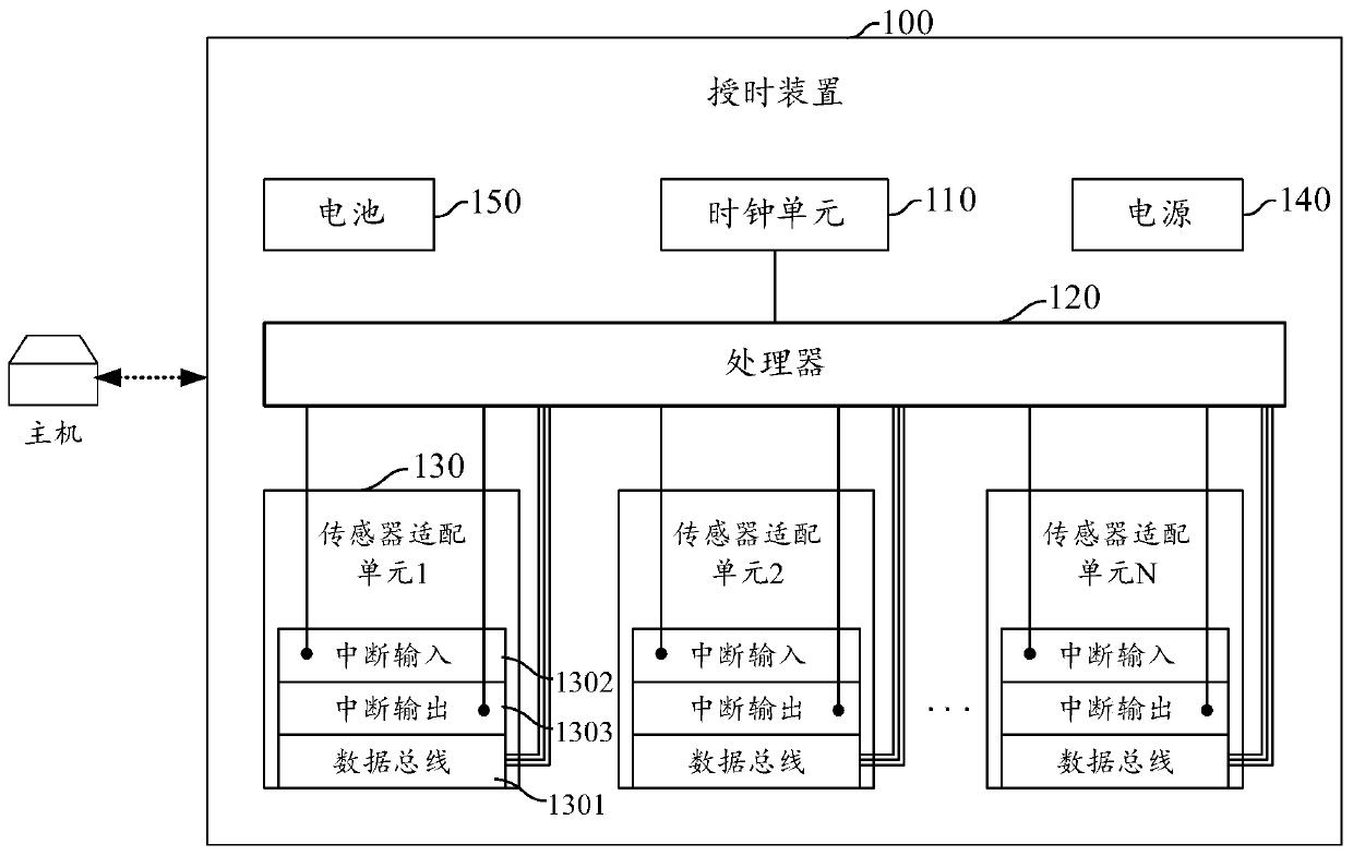
[0043] see figure 1 , which is a schematic diagram of the timing device provided in Embodiment 1 of the present invention, such as figure 1 As shown, the timing device 100 may include: a clock unit 110, a processor 120, and a sensor adaptation unit 130; the sensor adaptation unit 130 may include a data bus 1301; wherein the clock unit 110 is used to provide the processor 120 Clock signal; Processor 120 is used to generate a time synchronization signal according to the current time of the system, and the time synchronization signal is sent to the time-serving device connected to the sensor adaptation unit 130 through the bus 1301; the data bus 1301 is used for the processor 120 and The timing equipment connected to the sensor adaptation unit 130 provides a data transmission connection; the sensor adaptation unit 130 is used for connecting the timing equipment. During specific work, the clock unit 110 is used to provide an accurate clock signal for the processor 120 to ensure t...
Embodiment approach
[0046] When the time service device implements time service to a certain device node, the processor 120 can send the time synchronization signal to the time synchronization device connected to the sensor adaptation unit through the data bus, and the time service device can synchronize the arrival time of the signal according to the time And the correct time included in the time synchronization signal, determine the clock correction parameters of the device to be timed, and then correct the clock of the sensor node device according to the determined clock correction parameters. In another implementation manner, in order to enable the device to be timed to process the time synchronization task in a timely manner when receiving the time synchronization signal, an interrupt triggering method may be adopted. The processor 120 may include an interrupt signal in the time synchronization signal sent to the timing device connected to the sensor adaptation unit 130. Specifically, the pro...
Embodiment 2
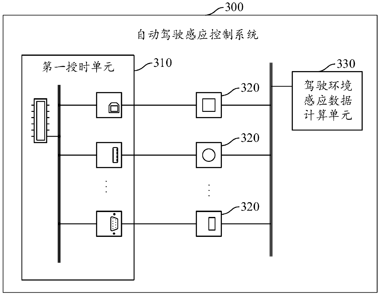
[0056] Embodiment 2 of the present application provides an automatic driving sensing control system, which is applied in the field of automatic driving sensing control. Please refer to image 3 , a schematic diagram of the automatic driving sensing control system provided in Embodiment 2 of the present application, as shown in image 3 As shown, the automatic driving sensing control system 300 may include a first timing unit 310, a driving environment sensor node 320, and a driving environment sensing data calculation unit 330; wherein, the first timing unit 310 may be used to provide timing for the driving environment sensor node . The driving environment sensor node 320 can determine the device local time of the driving environment sensor node according to the timing of the first timing unit, and use the calibrated device local time when performing environment perception to generate environment perception data, that is, the driving environment sensor node is used to sense th...
PUM
 Abstract
Description
Claims
Application Information
 - R&D
- Intellectual Property
- Life Sciences
- Materials
- Tech Scout
- Unparalleled Data Quality
- Higher Quality Content
- 60% Fewer Hallucinations
Browse by: Latest US Patents, China's latest patents, Technical Efficacy Thesaurus, Application Domain, Technology Topic, Popular Technical Reports.
© 2025 PatSnap. All rights reserved.Legal|Privacy policy|Modern Slavery Act Transparency Statement|Sitemap|About US| Contact US: help@patsnap.com


