
Intelligent full-automatic aquaculture material-feeding device and material feeding method thereof

A technology for aquaculture and feeding devices, applied in the direction of outboard propulsion devices, propulsion device engines, chemical instruments and methods, etc., can solve the problems of water quality reduction, reunion, etc., and achieve the effect of avoiding clogging

Inactive Publication Date: 2020-09-01
江苏叁拾叁信息技术有限公司
View PDF0 Cites 1 Cited by
  • Summary
  • Abstract
  • Description
  • Claims
  • Application Information

AI Technical Summary

Problems solved by technology

[0003] However, because of the phenomenon of agglomeration and other phenomena in the granule in the silo, if there is no treatment when discharging, the discharge port will be blocked first, and the water quality will be reduced secondly.

Method used


Image

  • Intelligent full-automatic aquaculture material-feeding device and material feeding method thereof
  • Intelligent full-automatic aquaculture material-feeding device and material feeding method thereof
  • Intelligent full-automatic aquaculture material-feeding device and material feeding method thereof

Examples


Embodiment 1

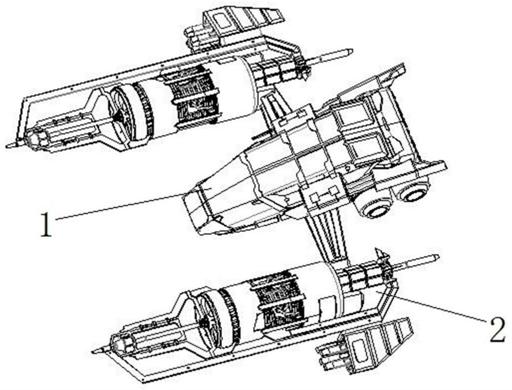
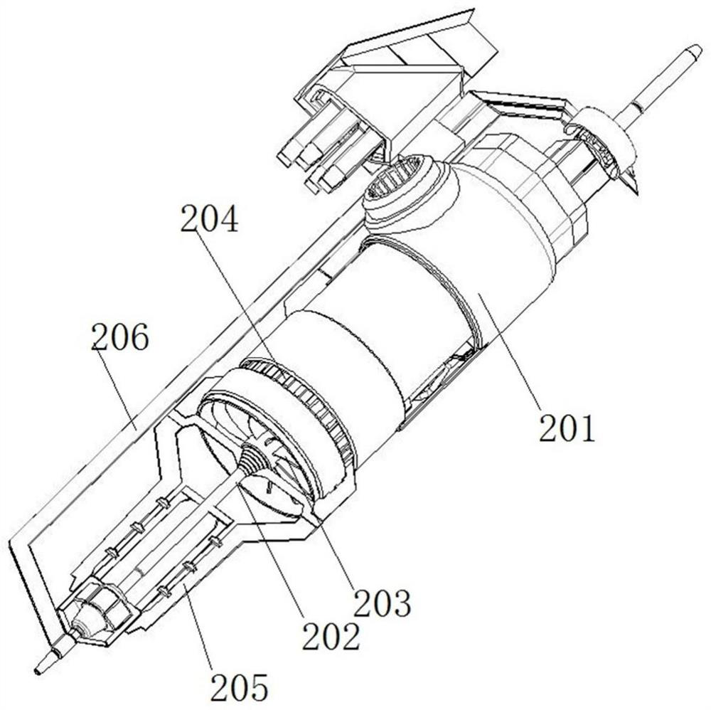
[0043] Such as figure 1 As shown, power propellers 2 are installed symmetrically on both sides of the hull 1 . Specifically, the structure of the power propeller 2 is as follows figure 2As shown, it includes: a cylindrical casing 201, the inside of which is a hollow structure. It also includes: a first rotating electrical machine with power, the first rotating electrical machine is fixed on the cylindrical housing 201, the output shaft of the first rotating electrical machine is connected with a rotating shaft 202, and the rotating shaft 202 is located on the Rotating blades 203 are tightly installed at the end of the cylindrical shell 201 , and the rotating blades 203 rotate under the drive of the first rotating motor to generate water flow and air flow, and play a role in pushing the hull 1 .

[0044] In order to solve the problem that water tanks are easy to breed at the corners of the pond mentioned above, which will cause the pontoon to be entangled, a cleaning assembl...

Embodiment 2

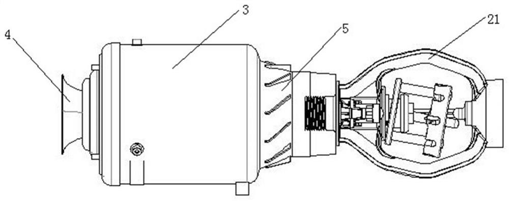
[0053] In the above-mentioned embodiment 1, the material with larger particles separated by the platform separation ring 16 still stays in the cavity 3 and needs to be effectively dissolved and dispersed by itself before entering the platform separation ring 16 for spraying. This process is slow, so the inventor made further improvements to the mixed flow assembly in order to speed up the dissolution.

[0054] Such as Figure 7 As shown, the mixed flow assembly further includes: the inside of the return cavity 5 is provided with a vane disc 18, the inner wall of the vane disc 18 is fixedly connected with the bottom of the transmission rod, and the spacer ring 16 of the table body A spring ring 15 is sleeved therein, and the spring ring 15 shakes in combination with the air flow and the liquid flow in the cavity 3 under the rotation of the blade disk 18 . In order to control the material can only flow through the discharge port from the inside of the table body partition ring ...


PUM


Abstract

The invention discloses an intelligent full-automatic aquaculture material-feeding device and a material feeding method thereof, and belongs to the technical field of aquaculture. The device includesa hull, two power propellers, N silos, a material mixing chamber and a nozzle assembly, wherein the two power propellers are symmetrically installed on both sides of the hull, the N silos are adjacently fixed on the hull through brackets, and the silos are separately used for accommodating materials of particles, powder, tablets and liquids; and the material mixing chamber is arranged horizontallybelow the silos, and communicates with the outlets of the silos at the same time through connecting pipes, and the nozzle assembly is fixed at the outlet of the material mixing chamber, and extends out of the hull, and is used for spraying the materials in the material mixing chamber into a pool. The material mixing chamber is arranged before spraying, the material mixing chamber is capable of fully mixing granular materials with a liquid on the premise of no damage to the granular materials, and can also be used for separating the granular materials according to the particle size, small granules can be sprayed directly, and large granules must be turned into small granules, and then are sprayed, so that the problem of clogging of nozzles is solved, and large-area spraying is achieved.

Description

technical field [0001] The invention belongs to the technical field of aquaculture, and in particular relates to an intelligent automatic aquaculture feeding device and a feeding method thereof. Background technique [0002] In the technical field of aquaculture, in order to ensure the quality and efficiency of aquatic products, food is added during the feeding process and drugs are also added in proportion. However, whether it is food or medicine, it will include different physical forms such as granules, powders, tablets or liquids, so it needs to be stirred, diluted and other processes when it is put in, so that it can be quickly integrated into the water after being put in. [0003] However, because of the phenomenon of agglomeration and other phenomena in the granule in the silo, if there is no treatment when discharging, it will first block the discharge port, and secondly reduce the water quality. Contents of the invention [0004] In order to solve the technical p...

Claims


Application Information

Patent Timeline
Patent Type & Authority Applications(China)
IPC IPC(8): A01K61/80B01F13/10B01F15/00B01F15/02B63B35/00B63H5/08B63H20/32A01D44/00
CPCA01K61/80B63B35/00B63H5/08B63H20/32A01D44/00B63H2020/003B01F33/821B01F35/187B01F35/754Y02A40/81
Inventor 刘卫民孙崇明张梓强张立智吴玉涛
Owner 江苏叁拾叁信息技术有限公司
Learn More