System and method for positioning U-position of IT equipment fault cabinet in machine room
A technology for equipment failure and locating system, applied in manipulators, program-controlled manipulators, manufacturing tools, etc., can solve the problems of long residence time of mobile equipment, high cost of manipulators, and heavy configuration workload, and reduce the pressure of fault location inspection. , Simple configuration, cost-saving effect
- Summary
- Abstract
- Description
- Claims
- Application Information
AI Technical Summary
Problems solved by technology
Method used
Image
Examples
Embodiment 1
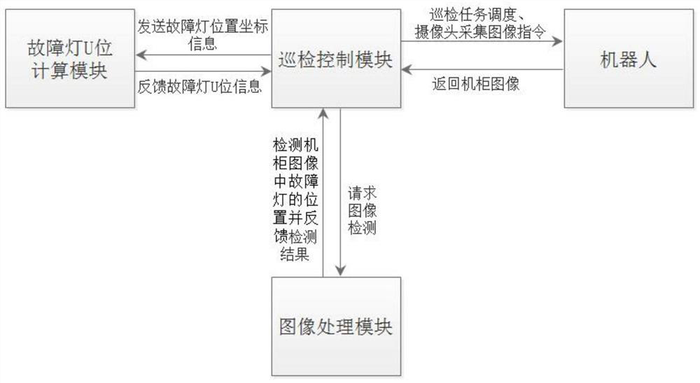
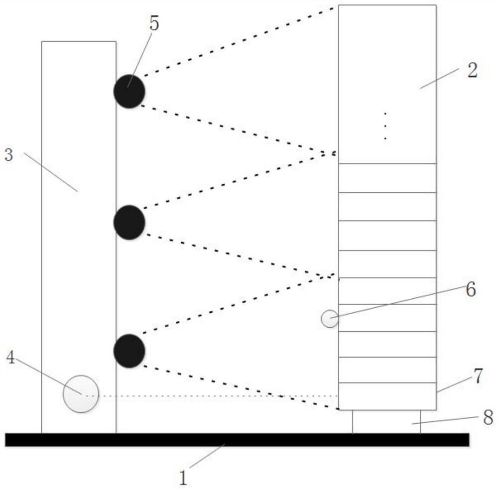
[0057] Such as figure 1As shown, a U-position positioning system for IT equipment fault cabinets in a computer room described in this embodiment includes a patrol control module, an image processing module, a fault light U-position calculation module, and at least one robot. The patrol control module is used for Scheduling inspection tasks for the robot, controlling the robot to collect cabinet images, and transmitting the collected cabinet images to the image processing module, the image processing module is used to detect the position of the fault light in the cabinet image and feed it back to the inspection control module, the The inspection control module is also used to transmit the position coordinate information of the fault light to the U position calculation module of the fault lamp, and the U position calculation module of the fault light is used to calculate the U position information of the cabinet where the fault light is located and to calculate the U position inf...
Embodiment 2
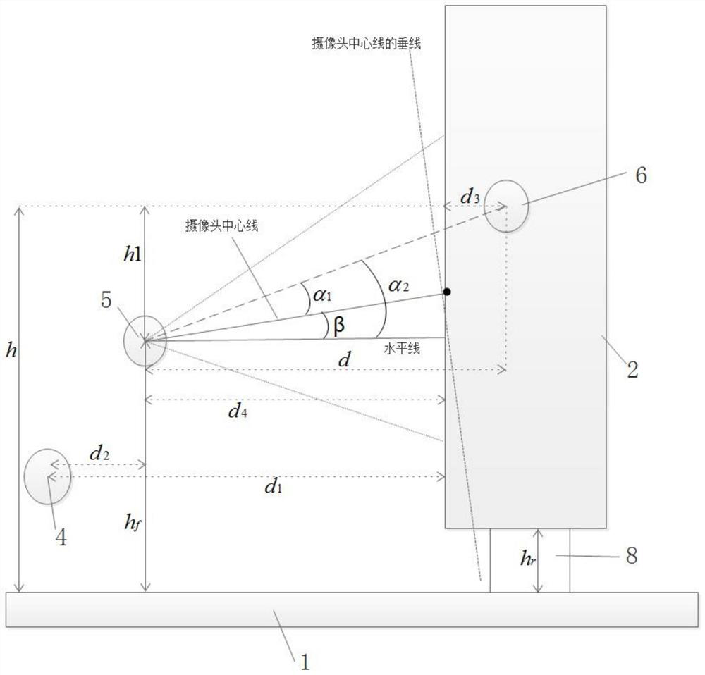
[0068] This embodiment provides a U-position positioning method based on the U-position positioning system for the computer room IT equipment failure cabinet U-positioning system described in Embodiment 1, such as image 3 with 4 shown, including the following steps:
[0069] S1. The robot moves to the front of the cabinet to be tested:
[0070] Specifically, the robot 3 navigates to the front of the cabinet 2 to be tested through the internal navigation module, and makes one of the cameras 5 face the cabinet 2 to be tested.
[0071] S2. The robot measures the distance between the robot and the cabinet 2 to be tested:
[0072] Specifically, the robot 3 measures the distance between the distance measuring device 4 and the door of the cabinet 2 to be tested through the distance measuring device 4 installed on the robot, denoted as d 1 .
[0073] S3. The camera on the robot takes pictures of the cabinet to be tested, and obtains the image of the cabinet to be tested:
[0074...
PUM
 Abstract
Description
Claims
Application Information
 - R&D
- Intellectual Property
- Life Sciences
- Materials
- Tech Scout
- Unparalleled Data Quality
- Higher Quality Content
- 60% Fewer Hallucinations
Browse by: Latest US Patents, China's latest patents, Technical Efficacy Thesaurus, Application Domain, Technology Topic, Popular Technical Reports.
© 2025 PatSnap. All rights reserved.Legal|Privacy policy|Modern Slavery Act Transparency Statement|Sitemap|About US| Contact US: help@patsnap.com


