Chemical sewage separation device
A separation device, sewage technology, applied in water/sewage treatment, water/sewage treatment equipment, water/sewage multi-stage treatment, etc., can solve the problems of inability to meet the use requirements, dosing, difficult to filter through the filter screen, etc., to achieve savings Space, high degree of mechanization, and the effect of improving separation efficiency
- Summary
- Abstract
- Description
- Claims
- Application Information
AI Technical Summary
Problems solved by technology
Method used
Image

Examples
Embodiment 1
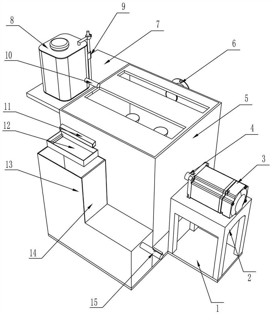
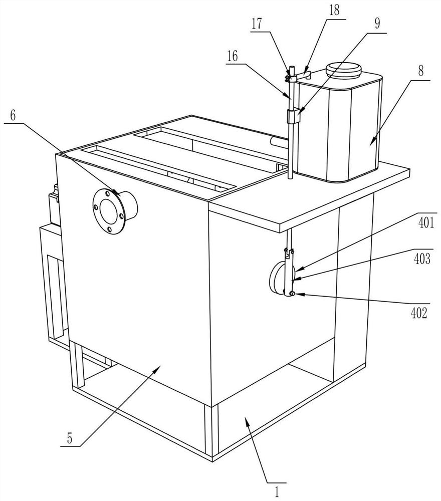
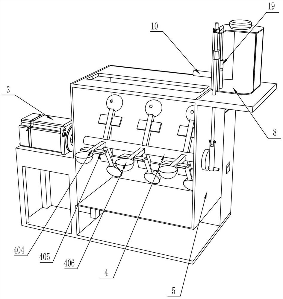
[0027] Such as Figure 1-Figure 3 As shown, a chemical sewage separation device includes a base 1, a support frame 2, a motor 3, a rotating shaft 4, a stirring mechanism, a treatment box 5, a water inlet pipe 6, a mounting plate 7, a medicine box 8, and a first sliding sleeve 9 , drug delivery pipe 10, drain pipe 11, filter box 12, water collection tank 13, partition 14, water outlet pipe 15, slide bar 16, second sliding sleeve 17, movable bar 18 and plug 19, the upper surface of base 1 is welded There is a support frame 2, the top of the support frame 2 is fixed with a motor 3 by bolts, the left end of the output shaft of the motor 3 is welded with a rotating shaft 4, the outer surface of the rotating shaft 4 is provided with a stirring mechanism, and the left side of the support frame 2 is provided with a processing box 5, The bottom inwall of processing case 5 is provided with dividing plate 14, and rotating shaft 4 passes processing case 5, and the upper rear side of proce...
Embodiment 2
[0032] On the basis of Example 2, such as Figure 4-Figure 5 Shown, also include first push rod 20, chute frame 21, slide rail 22, rack 23, water retaining plate 24, shovel plate 25, sewage collecting box 26, sewage door 27, the 3rd fixed rod 28, the 3rd A gear 29, a fixed plate 30, a rotating ring 31, a nut 32, a second gear 33 and a screw rod 34, the left end of the first fixed rod 402 is fixed with the first push rod 20 by bolts, and the left side of the first push rod 20 is slidably connected There is a chute frame 21, the upper front side of the processing box 5 is fixed with a slide rail 22 by bolts, the inside of the slide rail 22 is slidingly connected with a rack 23, and the right side of the drain pipe 11 is provided with a plug hole, and the plug hole is inserted A water baffle 24 is connected, a shovel plate 25 is provided inside the filter box 12, a sewage collection box 26 is fixed on the front outer wall of the water collection box 13 by bolts, and a sewage disc...
Embodiment 3
[0035] On the basis of Example 2, such as Figure 6-Figure 8 Shown, also include mounting frame 35, the second push rod 36, slide plate 37, positioning plate 38, swing plate 39 and ejector rod 40, the outer surface of screw rod 34 is sleeved with mounting frame 35, and the front side of mounting frame 35 rotates A second push rod 36 is connected, and the right end of the second push rod 36 is connected with a slide plate 37 in rotation, and the right side of the slide plate 37 is connected with a swing plate 39 in rotation, and the front and rear sides of the dirt collection box 26 are all fixed with a positioning plate 38 by bolts. , The left side inner wall of the dirt collection box 26 is fixed with a push rod 40 by bolts.
[0036] Also comprise torsion spring 41, top plate 42 and elastic member 43, be provided with torsion spring 41 between slide plate 37 and swing plate 39, the left and right sides inner walls of dirt collecting box 26 all offer chute, slide and connect w...
PUM
 Abstract
Description
Claims
Application Information
 - R&D
- Intellectual Property
- Life Sciences
- Materials
- Tech Scout
- Unparalleled Data Quality
- Higher Quality Content
- 60% Fewer Hallucinations
Browse by: Latest US Patents, China's latest patents, Technical Efficacy Thesaurus, Application Domain, Technology Topic, Popular Technical Reports.
© 2025 PatSnap. All rights reserved.Legal|Privacy policy|Modern Slavery Act Transparency Statement|Sitemap|About US| Contact US: help@patsnap.com