System of recycling wasteheat of aero-engine

An aero-engine, waste heat recovery technology, applied in engine components, engine cooling, machines/engines, etc., can solve problems such as low efficiency and large loss of compressed airflow, reduce air loss, solve cooling problems, and improve energy efficiency. Effect

Inactive Publication Date: 2020-09-01
TECHNICAL INST OF PHYSICS & CHEMISTRY - CHINESE ACAD OF SCI
View PDF5 Cites 0 Cited by
  • Summary
  • Abstract
  • Description
  • Claims
  • Application Information

AI Technical Summary

Problems solved by technology

[0004] The purpose of the present invention is to provide an aero-engine waste heat recovery and utilization system to solve the problems of large compressed air flow loss and low efficiency in existing aero-engines

Method used


Image

  • System of recycling wasteheat of aero-engine
  • System of recycling wasteheat of aero-engine
  • System of recycling wasteheat of aero-engine

Examples


Embodiment Construction

[0024] In order to make the purpose, technical solutions and advantages of the embodiments of the present invention clearer, the technical solutions in the embodiments of the present invention will be clearly and completely described below in conjunction with the drawings in the embodiments of the present invention. Obviously, the described embodiments It is a part of embodiments of the present invention, but not all embodiments. Based on the embodiments of the present invention, all other embodiments obtained by persons of ordinary skill in the art without making creative efforts belong to the protection scope of the present invention.

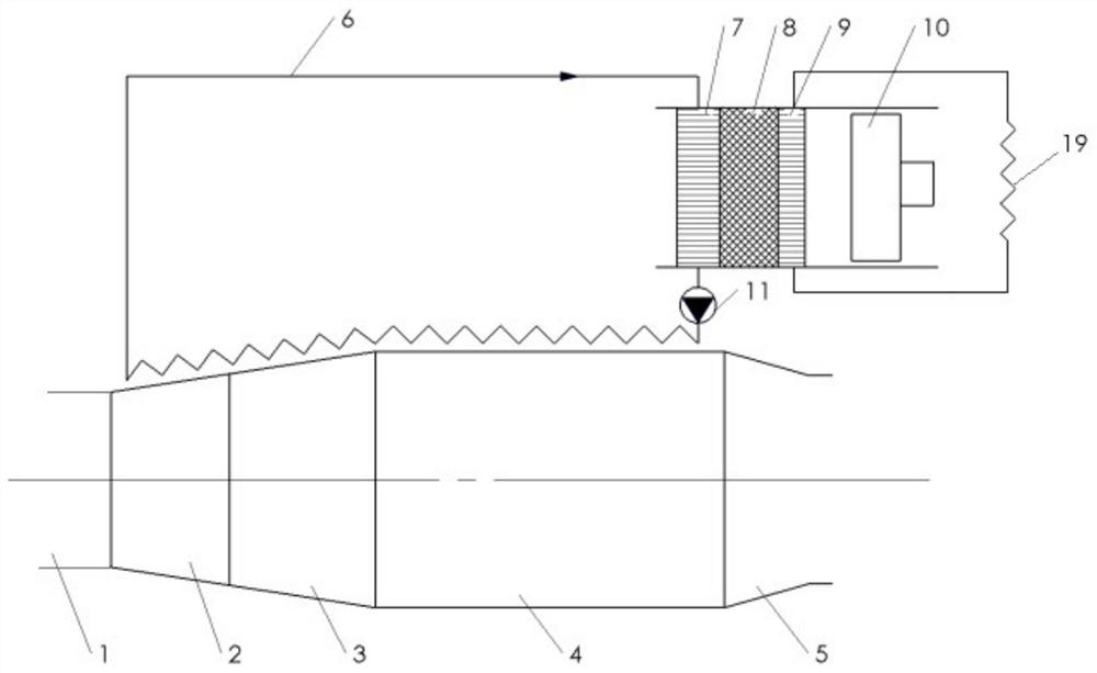
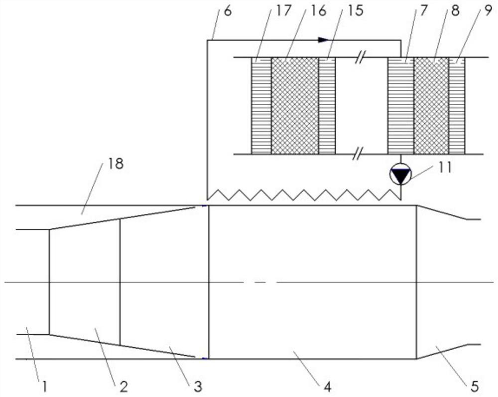
[0025] Such as Figure 1-3 As shown, the embodiment of the present invention provides an aeroengine waste heat recovery system, which at least includes an aeroengine, a thermoacoustic engine and a heat transfer fluid pipeline 6 .

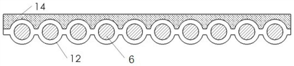
[0026] Wherein, a part of the heat-carrying fluid pipeline 6 is attached to the casing of the aero-engine, and ...


PUM


Abstract

The invention relates to the technical field of engines, in particular to a system of recycling wasteheat of an aero-engine. The system of recycling the wasteheat of the aero-engine comprises the aero-engine, a thermo-acoustic engine and a heat carrying fluid pipeline. A part of the heat carrying fluid pipeline and a housing of the aero-engine are arranged in a fit manner, and the two ends of theheat carrying fluid pipeline are correspondingly connected to a heat carrying fluid inlet and a heat carrying fluid outlet of the thermo-acoustic engine. The system of recycling the wasteheat of the aero-engine provided by the invention can drive the thermo-acoustic engine to work by mean of heat transferred to the housing by air flow in the aero-engine so as to convert heat energy into mechanicalenergy, so that heat when the aero-engine works is recovered and the energy utilization ratio of the aero-engine is improved, and meanwhile, the gas quantity loss for cooling the housing of the aero-engine is reduced, the cooling problem of the aero-engine is solved effectively, the integral performance of the aero-engine is improved, and the system meets different demands of an aircraft.

Description

technical field [0001] The invention relates to the technical field of engines, in particular to an aeroengine waste heat recovery and utilization system. Background technique [0002] The aero engine is the heart of the aircraft, providing power for the entire aircraft. However, the thermal efficiency of current aero-engines is very low due to the high temperature of the exhaust heat. When the aeroengine is working, the airflow entering the aeroengine inlet is mainly divided into two parts after being compressed and boosted by the intake compression section, one part enters the combustion section, and the other part enters the shell interlayer of the engine as a cooling airflow. After the airflow entering the combustion section burns and expands in the combustion section, it pushes the expansion turbine in the expansion section to do work, and accelerates into the afterburner, where it further burns with the injected fuel to raise its temperature, and accelerates the injec...

Claims


Application Information

Patent Timeline
Patent Type & Authority Applications(China)
IPC IPC(8): F02C6/18F02C7/16F03G7/00
CPCF02C6/18F02C7/16F03G7/00
Inventor 胡剑英罗二仓吴张华陈燕燕张丽敏
Owner TECHNICAL INST OF PHYSICS & CHEMISTRY - CHINESE ACAD OF SCI
Why Eureka
Try Eureka