
PSD used for laser autocollimator

An autocollimator and laser technology, applied in the field of sensor technology, can solve the problems of small angle range and poor precision

Pending Publication Date: 2020-09-01
深圳达瑞鑫光电科技有限公司
View PDF0 Cites 0 Cited by
  • Summary
  • Abstract
  • Description
  • Claims
  • Application Information

AI Technical Summary

Problems solved by technology

[0005] The invention provides a PSD used in a laser autocollimator, which solves the problems of small angle range and poor precision

Method used


Image

  • PSD used for laser autocollimator
  • PSD used for laser autocollimator
  • PSD used for laser autocollimator

Examples


no. 1 example

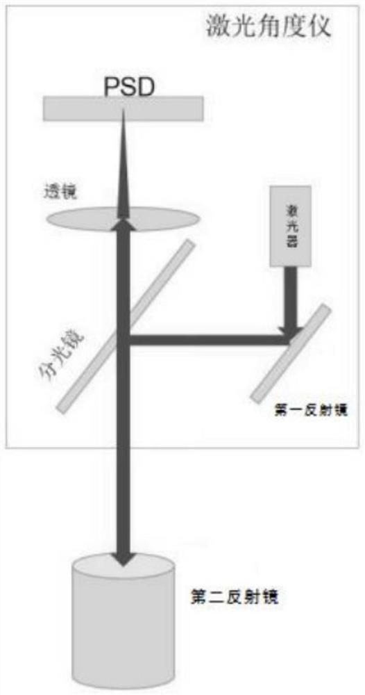
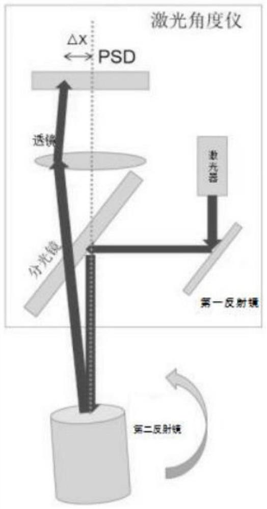
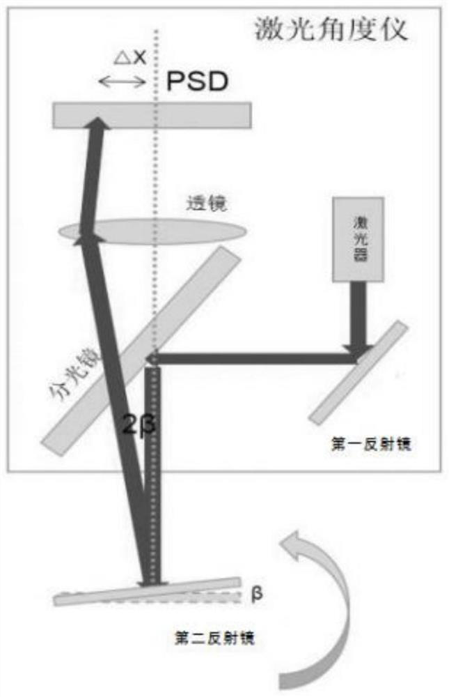
[0027] Please refer to figure 1 , figure 2 , image 3 ,in, figure 1 The PSD provided by the present invention is used for the structural representation of the first embodiment of the laser autocollimator; figure 2 The PSD provided by the present invention is used for the principle block diagram of the second reflector of the laser autocollimator tilting a certain angle; image 3 The PSD provided by the present invention is a functional block diagram for the second mirror of a laser autocollimator to tilt at a certain angle. PSD for laser autocollimator includes: laser 1, first reflector 2, beam splitter 3, second reflector 4, lens 5, PSD6;

[0028] The laser 1 emits a beam of collimated light that passes through the first reflector 2 and the beam splitter 3 to vertically split the beam into the mirror surface of the second reflector 4. The mirror 3 hits the center of the PSD6 through the optical axis of the lens 5, and this state represents 0 angle.

[0029] PSD is com...

no. 2 example

[0039] Please refer to Figure 4-Figure 6 , based on the PSD provided in the first embodiment of the present application for the laser autocollimator, the second embodiment of the present application proposes another PSD for the laser autocollimator. The second embodiment is only a preferred mode of the first embodiment, and the implementation of the second embodiment will not affect the independent implementation of the first embodiment.

[0040] Specifically, the PSD provided by the second embodiment of the present application is used for a laser autocollimator. 7 The other side of the top is fixedly connected with a second support rod 9, the top of the first support rod 8 is fixedly connected with a first mounting plate 10, and the top of the second support rod 9 is fixedly connected with a second mounting plate 11 , the top of the base 7 is fixedly connected with a first fixed block 12, the second reflector 4 is movably connected with the top of the first fixed block 12, ...


PUM


Abstract

The invention provides a PSD used for a laser autocollimator. The PSD used for the laser autocollimator comprises a laser, a first reflector, a spectroscope, a second reflector, a lens and a PSD body.A beam of collimated light emitted by the laser passes through the first reflector and the spectroscope and vertically enters the mirror surface of the second reflector in a light splitting mode, thelight is reflected by the mirror surface and then is reflected back to pass through the spectroscope along the original path, the light is emitted to the center of the PSD through the optical axis ofthe lens, and the state represents the angle of zero. The PSD used for the laser autocollimator, which is provided by the invention, has a high-precision effect, the precision can reach 0.4% of an angle range, and the resolution is as high as 0.02%; the PSD has a high-speed effect, RS485 communication is adopted, the speed can reach 1 KHz; and the defects that the speed is low, the angle range issmall, the precision is poor, interference of the external environment is large, and rear-end processing software is complex are overcome.

Description

technical field [0001] The invention relates to the application field of sensor technology, in particular to a PSD used for a laser autocollimator. Background technique [0002] Autocollimator is an important optical precision angle measuring instrument, which is widely used in machinery manufacturing, shipbuilding, aerospace, metrology testing, scientific research and other fields. A new photoelectric detection device is applied to the autocollimator system to form a photoelectric autocollimator. [0003] The existing solutions use CCD or CMOS as the sensor. The existing technology mainly has the disadvantages of slow speed, small angle range, poor precision, large interference from the external environment, and complex back-end processing software. [0004] Therefore, it is necessary to provide a PSD for laser autocollimator to solve the above technical problems. Contents of the invention [0005] The invention provides a PSD used in a laser autocollimator, which solve...

Claims


Application Information

Patent Timeline
Patent Type & Authority Applications(China)
IPC IPC(8): G01C15/00
CPCG01C15/004
Inventor 温永达
Owner 深圳达瑞鑫光电科技有限公司
Learn More