A cabling device for power cable production and a method of using the same

A power cable and cabling technology, applied in conductor/cable supply devices, cable/conductor manufacturing, circuits, etc., can solve the problems of loose winding, uneven force on cables, affecting cabling, etc., to ensure the effect of cabling , space saving, reasonable structure effect

Active Publication Date: 2022-04-12
福建鼎力电缆科技有限公司
View PDF18 Cites 0 Cited by
  • Summary
  • Abstract
  • Description
  • Claims
  • Application Information

AI Technical Summary

Problems solved by technology

[0003] In the common cable forming machines, they are all horizontal equipment. When forming cables, the cable core will be affected by gravity, resulting in a certain arc, resulting in uneven stress on the cables of all parties, and the in-line When the cable is wound, if the wire is paid out too fast, the inertia will pull out the cable at the rear end, resulting in loose winding and affecting the cable formation.

Method used


Image

  • A cabling device for power cable production and a method of using the same
  • A cabling device for power cable production and a method of using the same
  • A cabling device for power cable production and a method of using the same

Examples


Embodiment 1

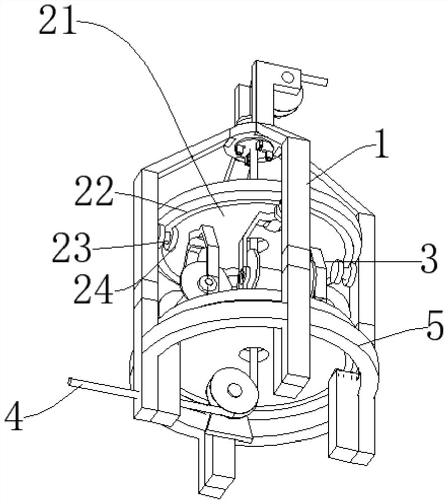
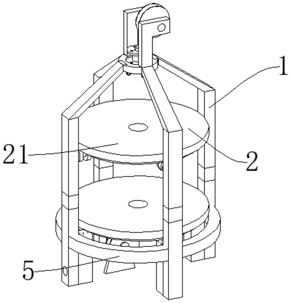
[0049] Such as Figure 1-Figure 8 , as shown, the transmission mechanism 7 includes a passive bevel gear 71, an active bevel gear 72, a transmission rod 73, and a motor 74. The passive bevel gear 71 is connected to the transmission gear 23 of the rotating mechanism 2, the active bevel gear 72 is connected to the passive bevel gear 71, and the active bevel gear 72 is connected to the passive bevel gear 71. The power end of gear 72 is connected to transmission rod 73, and the power end of transmission rod 73 is connected to motor 74. 71, so that the driven bevel gear 71 drives the transmission gear 23 to rotate, and the transmission gear 23 cooperates with the gear bar 22 at the lower end of the rotating disk 21 after rotating, thereby driving the rotating disk 21 to rotate; the supporting mechanism 1 includes a column 11, an upper wheel mounting frame 12, a lower end Guide wheel 13, upper end guide wheel 14, column 11 upper end connects upper wheel installation frame 12, connec...

Embodiment 2

[0052] Such as Figure 9 The difference between this embodiment and Embodiment 1 is that the transmission mechanism 7 includes a worm wheel 711, a worm 712, and a motor 74, and the motor 74 is connected to the inside of the column 11 of the support mechanism 1, and the output end of the motor 74 is connected to the worm 712, and the worm 712 is connected to two The worm gear 711, the output end of the worm gear 711 is connected to the transmission gear 23 of the rotating mechanism 2, the motor 74 drives the worm 712 to rotate, the worm 712 meshes with the worm gear 711, thereby driving the transmission gear 23 to rotate, after the transmission gear 23 rotates, it cooperates with the gear bar at the lower end of the rotating disk 21 22, thereby driving the rotating disc 21 to rotate.

[0053] A method for using a cabling device for power cable production, characterized in that it includes the following steps:

[0054] a. Pass the cable 4 through the lower guide wheel 13, the h...


PUM


Abstract

The invention discloses a cable forming device for power cable production and a method for using the same, which includes a cable, a support mechanism for supporting, a pay-off mechanism for vertical cable formation, and a pay-off mechanism for adjusting the cable. The tension mechanism of the pay-off speed, the support mechanism is equipped with a rotation mechanism, the rotation mechanism is connected to the pay-off mechanism, the tension mechanism is connected inside the pay-off mechanism, the support mechanism and the rotation mechanism They are connected by a transmission mechanism, and the power end of the rotating mechanism is connected with a linkage mechanism. The structure of the invention is reasonable, and the device adopts the structure of vertical laying and cabling, which avoids the radian formed by the central cable receiving gravity during horizontal cabling, avoids the influence of stress on the cable, and ensures the cabling effect of the cable , and save space, and use the cooperation of the elastic mechanism and the pay-off mechanism to accurately control the pay-off speed, thereby ensuring the tightness of the external cable.

Description

technical field [0001] The invention relates to the field of cable production, in particular to a cable forming device for power cable production and a method for using the same. Background technique [0002] The cable forming machine is the main equipment for the production of power cables, plastic cables and rubber cables in wire and cable factories. The cable forming machine is a complete set of equipment specially used to manufacture four-core, five-core plastic, cross-linked cables and armored cables with a cross-sectional area of ​​25-240mm square. It is redesigned with reference to the advanced cabling equipment at home and abroad, combined with the actual situation of wire and cable production in my country. Its structure is composed of transmission device, twisted cage, double-row wire mold base, wrapping head, steel belt head, meter counter, traction device, wire take-up rack, electrical control and other parts. [0003] In the common cable forming machines, they...

Claims


Application Information

Patent Timeline
Patent Type & Authority Patents(China)
IPC IPC(8): H01B13/00
CPCH01B13/0036H01B13/0003
Inventor 林骁张弛林骏煌
Owner 福建鼎力电缆科技有限公司
Why Eureka
Try Eureka