
Novel low-voltage high-frequency band inverter circuit

An inverter circuit and low-voltage technology, which is applied in the field of power systems, can solve problems such as high cost, complex structure, and large volume and weight, and achieve the effects of convenient debugging, simple structure, and fast frequency response

Pending Publication Date: 2020-09-01
SHANGHAI ZITONG INFORMATION TECH
View PDF0 Cites 0 Cited by
  • Summary
  • Abstract
  • Description
  • Claims
  • Application Information

AI Technical Summary

Problems solved by technology

This principle has disadvantages such as complex structure, high cost, large volume and weight, troublesome debugging and parameter calculation, etc.
Very unsuitable for mass production and maintenance under low power conditions

Method used


Image

  • Novel low-voltage high-frequency band inverter circuit

Examples


Embodiment Construction

[0027] The present invention will be described in detail below in conjunction with specific embodiments and accompanying drawings, and the embodiments of the present invention will be described in further detail below in conjunction with the accompanying drawings, but this embodiment is not intended to limit the present invention. Similar structures and similar changes thereof should be included in the protection scope of the present invention, and commas in the present invention all represent the relationship between and.

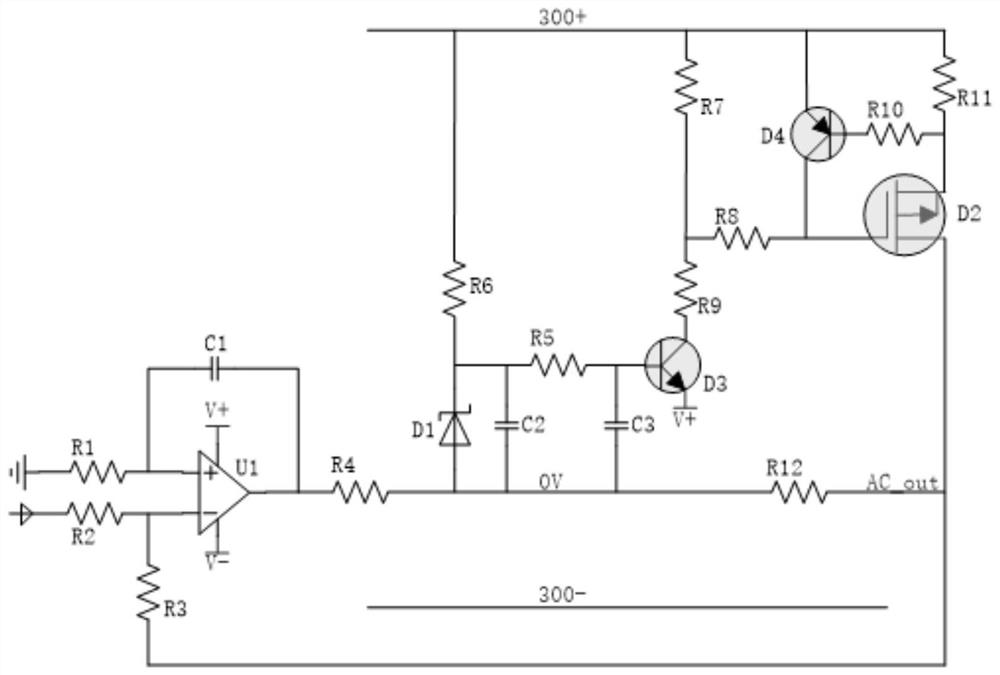
[0028] A new low-voltage high-frequency band inverter circuit, which includes a hysteresis comparator, an operational amplifier power supply, a power tube drive circuit, and a power tube protection circuit;

[0029] The negative pole of the hysteresis comparator input is connected to the reference input R2 and the feedback input R3, the positive pole forms an integral relationship with the matching resistor R1 and the capacitance of C1, and the output of th...


PUM


Abstract

The invention discloses a novel low-voltage high-frequency band inverter circuit. A hysteresis comparison input negative electrode is connected with a reference input R2 and a feedback input R3, a positive electrode is in integral association with a matching resistor R1 and a capacitor C1, and the output of a comparator directly drives a load resistor R4. The operational amplifier working power supply V + is connected to the emitting electrode of a triode D3, and the base electrode of the operational amplifier working power supply V + is connected with the reference voltage formed by a resistor, a voltage-regulator tube and a capacitor. A collector electrode of the operational amplifier power supply generation triode D3 is connected in series with a current-limiting resistor R9 and a driving resistor R7, and the two resistors are connected to a grid electrode of a power tube D2 through the current-limiting resistor after voltage division. A PNP triode, a current-limiting resistor R10 and a sampling resistor R11 form a power tube protection loop which is used for the real-time protection of the power tube D2. According to the invention, a brand-new inversion control idea is used, through the reasonable parameter design, hundreds of volt-amperes of power output can be provided for the loop, and the novel low-voltage high-frequency band inverter circuit has the advantages of fastfrequency response speed, simple structure, convenient debugging and the like.

Description

technical field [0001] The invention relates to an inverter circuit of electric power equipment, and relates to the technical field of electric power systems. Background technique [0002] The inverter circuit (Inverter Circuit) corresponds to the rectifier circuit (Rectifier), and the conversion of direct current into alternating current is called inverter. Inverter circuits can be used to form various AC power sources and are widely used in industry. [0003] Inverter circuits are widely used. Among the various existing power sources, storage batteries, dry batteries, solar cells, etc. are all DC power sources. When these power sources are required to supply power to AC loads, an inverter circuit is required. In addition, power electronic devices such as frequency converters for AC motor speed control, uninterruptible power supplies, and induction heating power supplies are widely used, and the core part of their circuits are inverter circuits. Its basic function is to ...

Claims


Application Information

Patent Timeline
Patent Type & Authority Applications(China)
IPC IPC(8): H02M7/537H02M1/32H02M1/08
CPCH02M1/08H02M1/32H02M7/537
Inventor 周文华闫兴浩王笑纵金龙鲍俊杰
Owner SHANGHAI ZITONG INFORMATION TECH
Learn More