Constant-tension wire conveying device and tension measurement method

A technology of constant tension and force measurement, which is applied in electric processing equipment, metal processing equipment, electrode manufacturing, etc., and can solve problems such as inability to accurately control the tension of the electrode wire, poor electrode wire tension, and short service life of the electrode wire.

Active Publication Date: 2018-06-01
顾元章
View PDF9 Cites 2 Cited by
  • Summary
  • Abstract
  • Description
  • Claims
  • Application Information

AI Technical Summary

Problems solved by technology

Further analysis found that: during reciprocating bidirectional movement, the dynamic tension of the electrode wire segment in the state of drawing wire is greater than that of the wire electrode segment in the state of unwinding wire. There are two states of wire unwinding, so between the upper first reversing wheel 36 and the lower first reversing wheel 37 installed at both ends of the first reversing arm 41, there is always an electrode that alternately changes direction as the wire feeding direction changes. Wire tension difference, after mechanical analysis, it will be multiplied by 1/2 length of the first reversing arm to form a moment; in this structure, the counter torque generated on the upper guide rail 111 and the lower guide rail 112 will automatically balance the torque ; Therefore, the upper and lower two parts of the electrode wire tension are not all applied to the load cell 31, resulting in measurement errors
T

Method used


Image

  • Constant-tension wire conveying device and tension measurement method
  • Constant-tension wire conveying device and tension measurement method
  • Constant-tension wire conveying device and tension measurement method

Examples


Embodiment 1

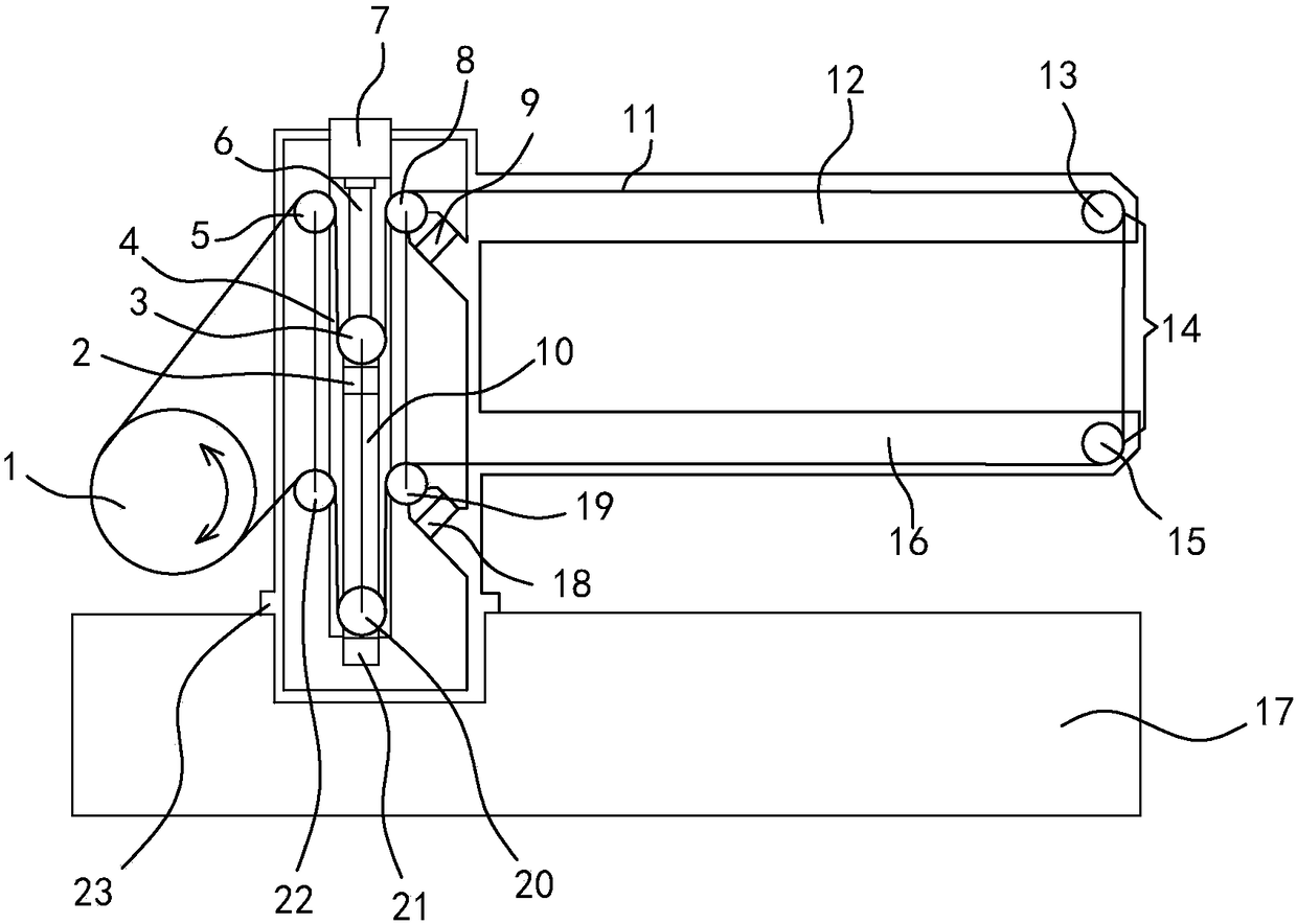
[0057] as attached figure 1 As shown, the wire storage drum 1 is fixed on the bed 17, the column 23 is vertically fixed on the plane of the bed 17, and the upper thread frame arm 12 and the lower thread frame arm 16 are fixedly installed on the upper and lower parts of the column 23 respectively horizontally. positional relationship such as figure 1 shown. The upper guide wheel 13 is rotatably supported on the front portion of the upper thread stand arm 12 , and the lower guide wheel 15 is rotatably supported on the front portion of the lower thread stand arm 16 . The upper row of wire wheels 5 and the lower row of wire wheels 22, which are used to neatly arrange and wrap the electrode wires 11 in the wire storage drum 1, are all rotatably supported on the column 23, and are respectively located on the left side of the single-axis industrial manipulator 4, that is, farther away from the wire storage drum 1. near side. The single-axis industrial manipulator 4 is vertically i...

Embodiment 2

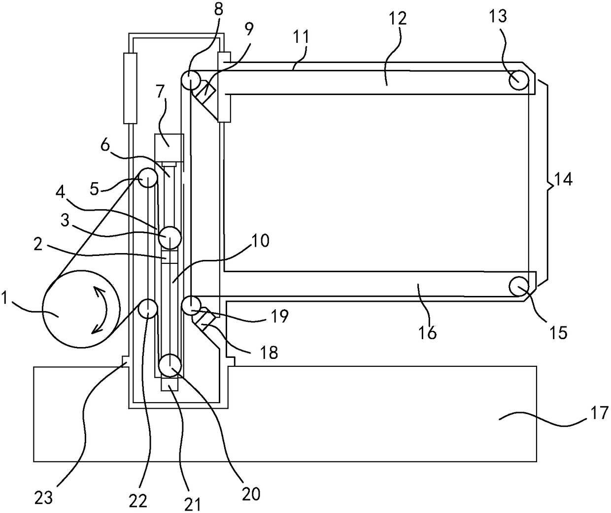
[0062] The difference between this embodiment and Embodiment 1 is that in this embodiment, in order to meet the requirements of cutting and processing workpieces with different thicknesses, the upper wire frame arm 12 can move vertically up and down along the column 23 according to the height of the workpiece, and then move The upper thread stand arm 12 is locked and fixed on the column 23 . The upper guide wheel 13 is rotatably supported on the front part of the upper wire rack arm 12; the second connection surface of the upper load cell 9 is fixed on the right inner side of the upper wire rack arm 12 which is slidingly combined with the column 23, and On the small inclined surface that protrudes at an angle of 45 degrees from the horizontal plane; after the upper wire frame arm 12 is positioned and locked, the axle of the upper force measuring wheel 8 is parallel to the plane of the bed 17, and is still on the same plane as the axle of the lower force measuring wheel 19 paral...

Embodiment 3

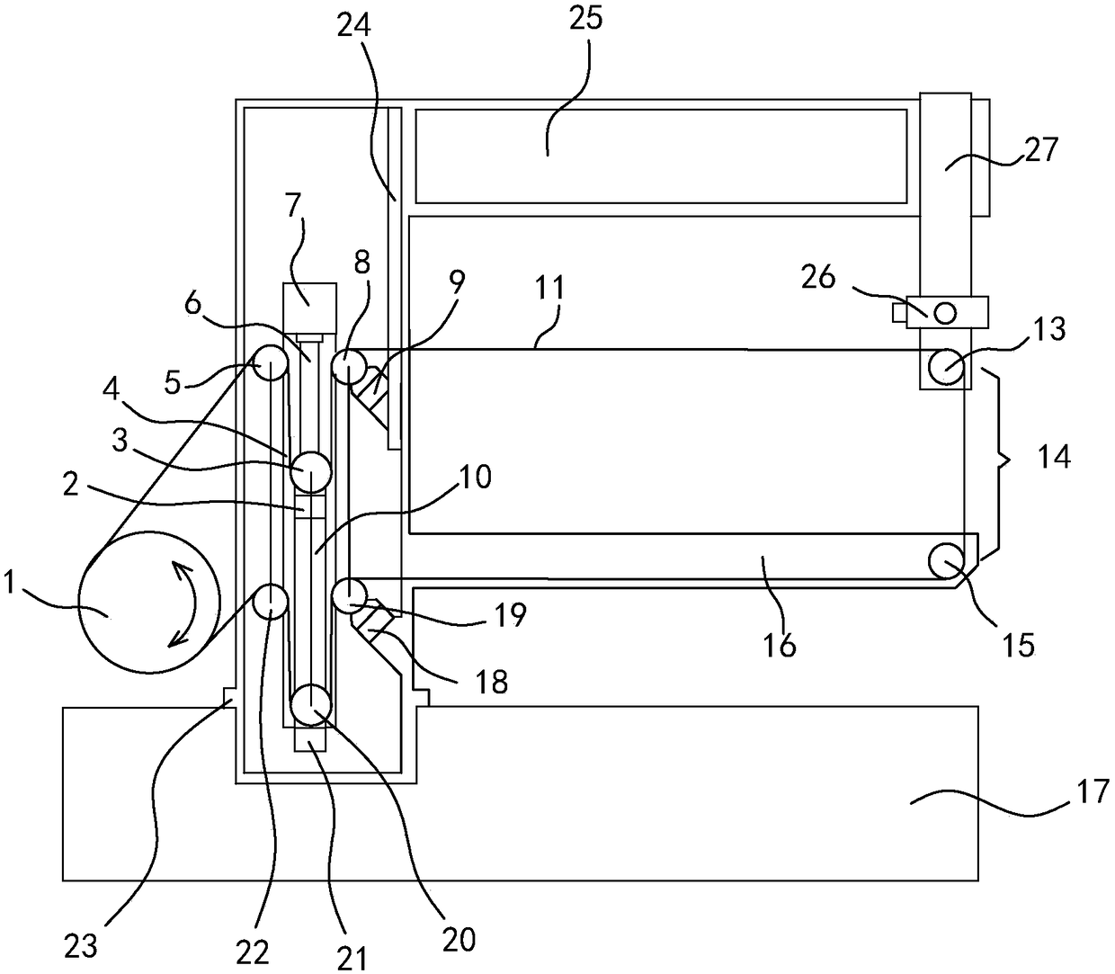
[0064] The difference between this embodiment and Embodiment 1 is that the traditional C-shaped wire frame 25 integrates the upper wire frame arm 12 and the column 23, and there is a wire frame at the front of the C-shaped wire frame 25 that can be used as an upper, The Z-axis 27 of lower lifting, the U-V carriage 26 that a cutting small taper workpiece is fixed below the Z-axis 27, and the upper guide wheel 13 is fixed on the lower carriage of the U-V carriage 26. In this embodiment, the second connection surface of the upper load cell 9 is fixed on a small inclined surface at an angle of 45 degrees to the horizontal plane on the slider of the lifting guide rail assembly 24; the lifting guide rail assembly 24 is fixed on the C-shaped wire frame On the right inner side of the vertical part of the vertical part, the lifting guide rail assembly 24 is synchronously lifted with the Z axis 27, so that the electrode wire between the upper guide wheel 13 and the upper force measuring ...


PUM


Abstract

The invention provides a constant-tension wire conveying device and a tension measurement method. The constant-tension wire conveying device comprises a wire storage cylinder, an electrode wire, an upper wire discharge wheel, a lower wire discharge wheel, a wire tightening mechanism, an upper guide wheel and a lower guide wheel. The constant-tension wire conveying device is characterized by further comprising an upper tension measurement wheel, an upper tension measurement sensor, a lower tension measurement wheel, a lower tension measurement sensor and a tension control circuit; the wire tightening mechanism comprises a connecting plate, a connecting plate driving device, an upper wire tightening wheel, an upper shock absorber, a lower wire tightening wheel and a lower shock absorber; onan electrode wire conveying path, the upper tension measurement wheel is located between the upper wire tightening wheel and the upper guide wheel, and the lower tension measurement wheel is located between the lower wire tightening wheel and the lower guide wheel; in the moving process of the connecting plate, the wrap angle where the electrode wire makes contact with the upper tension measurement wheel and the wrap angle where the electrode wire makes contact with the lower tension measurement wheel remain unchanged. Tension of the electrode wire at the upper end of an electric discharge machining area is transferred to the upper tension measurement sensor through the upper tension measurement wheel; the tension of the electrode wire at the lower end of the electric discharge machining area is transferred to the lower tension measurement sensor through the lower tension measurement wheel. The two parts of tension are added to serve as the basis for conducting constant-tension closed-loop control over the electrode wire.

Description

technical field [0001] The invention relates to a reciprocating wire-feeding type numerical control wire electric discharge cutting machine, in particular to a machine with two characteristics of constant tension control of electrode wire and stable wire feeding composed of three and two types of different functional mechanisms in series. wire device. Background technique [0002] Wire-cut electric discharge machine is a kind of special processing machine tool that uses thin metal wire as electric spark pulse discharge between the wire electrode and the workpiece, and uses the electric erosion effect generated by pulse discharge to carry out cutting processing. Constant wire electrode tension and stable wire feeding are two necessary conditions for this type of machine tool to obtain high processing efficiency and excellent processing quality. Foreign countries only produce unidirectional low-speed wire-feeding WEDM, which uses wire electrodes to move wire in one direction ...

Claims


Application Information

Patent Timeline
IPC IPC(8): B23H7/10
Inventor 顾元章
Owner 顾元章
Why Eureka
Try Eureka