Mobile magnetic resonance system

A magnetic resonance and mobile technology, which is applied in the fields of magnetic resonance measurement, motor vehicles, and magnetic variable measurement, can solve the problems of inconvenient scanning and examination of patients, and achieve the advantages of improved convenience and scope of use, compact structure, and easy mobile application Effect

Inactive Publication Date: 2020-09-04
RAY PLUS MEDICAL TECH CO LTD
View PDF0 Cites 1 Cited by
  • Summary
  • Abstract
  • Description
  • Claims
  • Application Information

AI Technical Summary

Problems solved by technology

[0003] In view of this, the present invention proposes a mobile magnetic resonance system, which aims to solve the problem that the fixed installation of the existing magnetic resonance system brings a lot of inconvenience to the scanning examination of the patient

Method used


Image

  • Mobile magnetic resonance system
  • Mobile magnetic resonance system
  • Mobile magnetic resonance system

Examples


Embodiment Construction

[0037] Exemplary embodiments of the present disclosure will be described in more detail below with reference to the accompanying drawings. Although exemplary embodiments of the present disclosure are shown in the drawings, it should be understood that the present disclosure may be embodied in various forms and should not be limited by the embodiments set forth herein. Rather, these embodiments are provided for more thorough understanding of the present disclosure and to fully convey the scope of the present disclosure to those skilled in the art. It should be noted that, in the case of no conflict, the embodiments of the present invention and the features in the embodiments can be mutually

[0038] combination. The present invention will be described in detail below with reference to the accompanying drawings and examples.

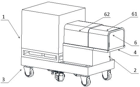
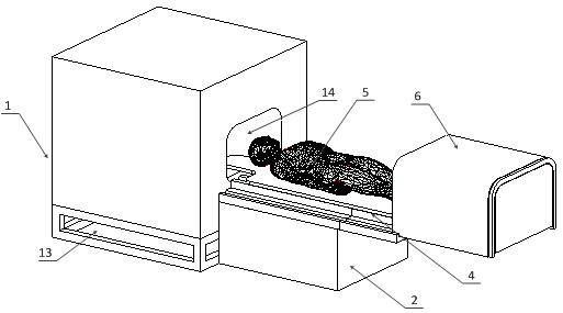
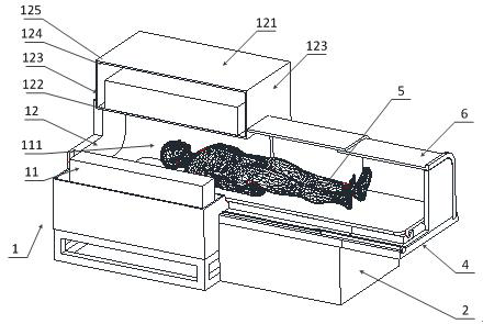
[0039] see Figure 1 to Figure 3 , which shows a preferred structure of the mobile magnetic resonance system provided by the embodiment of the present ...


PUM


Abstract

The invention provides a mobile magnetic resonance system. The mobile magnetic resonance system comprises a scanning mechanism, a conjoined cabinet, an omni-directional mobile chassis and a sickbed mechanism, wherein the scanning mechanism and the conjoined cabinet are arranged on the omni-directional moving chassis; the conjoined cabinet is arranged on one side of the scanning mechanism, and theconjoined cabinet is connected with the scanning mechanism; the scanning mechanism is provided with a cavity structure; the side wall of the scanning mechanism is provided with a first opening penetrating through the cavity structure, and the first opening is arranged towards the direction of the conjoined cabinet; and the sickbed mechanism is slidably connected in the cavity structure and on thetop wall of the conjoined cabinet. The conjoined cabinet is arranged on one side of the scanning mechanism, serves as the conjoined cabinet to support the sickbed mechanism, and also serves as a control cabinet of the scanning mechanism to save the sickbed mounting space; the scanning mechanism and the conjoined cabinet are integrally driven by the omni-directional moving chassis to move on the ground or a working surface, so that the magnetic resonance system is integrally moved to a first preset position, such as beside a patient bed, for magnetic resonance examination.

Description

technical field [0001] The present invention relates to the technical field of magnetic resonance, in particular to a mobile magnetic resonance system. Background technique [0002] At present, the magnetic resonance systems on the market are all in the form of fixed installation. The relevant functional components such as magnets need to be installed in a fixed magnetic resonance shielding room. The existing cabinets are relatively large, so they are placed outside the magnetic resonance shielding room. The functional components in the two positions are connected by cables. That is, the installation space of each hospital is different, so that the functional components of the magnetic resonance system will be installed separately and connected to each other through cables. This kind of system not only occupies a large area of ​​installation site, but also the scattered and chaotic structure of various functional components will bring certain difficulties to the installation...

Claims


Application Information

Patent Timeline
Patent Type & Authority Applications(China)
IPC IPC(8): A61B5/055B60B19/12B62D57/02G01R33/34G01R33/42H05K7/02
CPCA61B5/055B60B19/12B62D57/02G01R33/34G01R33/42H05K7/02
Inventor 连建宇王义槐郭金红王振李杰银张春光董聪坤薛德强万克家
Owner RAY PLUS MEDICAL TECH CO LTD
Why Eureka
Try Eureka