Printing and dyeing equipment for textiles

A technology for printing and dyeing equipment and textiles, applied in the field of printing and dyeing equipment for textiles, can solve the problems of long coloring process time and unsatisfactory effect, and achieve the effect of improving conveying uniformity, reducing water content and ensuring sealing

Inactive Publication Date: 2020-09-04
钱炜
View PDF0 Cites 2 Cited by
  • Summary
  • Abstract
  • Description
  • Claims
  • Application Information

AI Technical Summary

Problems solved by technology

[0004] The purpose of the present invention is to solve the defects of long coloring process and unsatisfactory effect in the prior art, and propose a kind of printing and dyeing equipment for textiles

Method used


Image

  • Printing and dyeing equipment for textiles
  • Printing and dyeing equipment for textiles
  • Printing and dyeing equipment for textiles

Examples


Embodiment 1

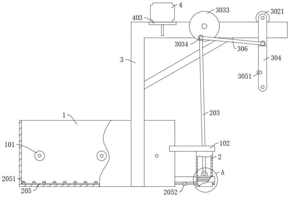
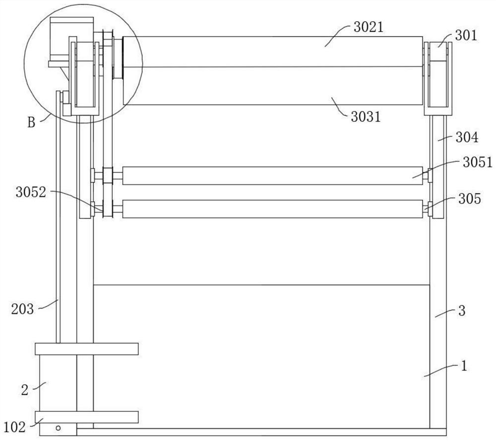
[0032] refer to Figure 1-5 , a printing and dyeing equipment for textiles, comprising a liquid storage tank 1 and a bracket 3 fixedly connected to the side wall of the liquid storage tank 1, an auxiliary roller 101 is rotatably connected in the liquid storage tank 1, and a blowing mechanism is arranged at the bottom of the liquid storage tank 1, The top of the support 3 is sequentially connected with a first rotating shaft 302 and a second rotating shaft 303 from top to bottom, and the first rotating shaft 302 is fixedly connected with a first pulley 3022 and a first roller 3021 in sequence from left to right, and the second rotating shaft 303 is fixedly connected with the second pulley 3032 and the second roller 3031 sequentially from left to right, the first pulley 3022 is connected with the second pulley 3032 through the rotation of the belt, and the top of the bracket 3 is fixedly connected with a pulley for driving the second pulley. The driving part of the wheel 3032 ro...

Embodiment 2

[0034] refer to figure 1 with Figure 4, is basically the same as that of Embodiment 1, furthermore, the drive unit includes a drive motor 4, a mount 403 is fixedly connected to the bracket 3, the drive motor 4 is fixedly connected to the mount 403, and the output end of the drive motor 4 is fixedly connected to a The drive shaft 401 is fixedly connected with the fourth pulley 402 on the drive shaft 401, and the fourth pulley 402 is rotationally connected with the second pulley 3032 by a belt, and the driving motor 4 utilizes the fourth pulley 402 to drive the second pulley 3032 to rotate. Realize sequential feeding, and when the humidity of the textile is too high to meet the coloring requirements, the conveying speed can be reduced by means of a low transmission ratio of the belt, so that the textile can swing several times and reduce the moisture content.

Embodiment 3

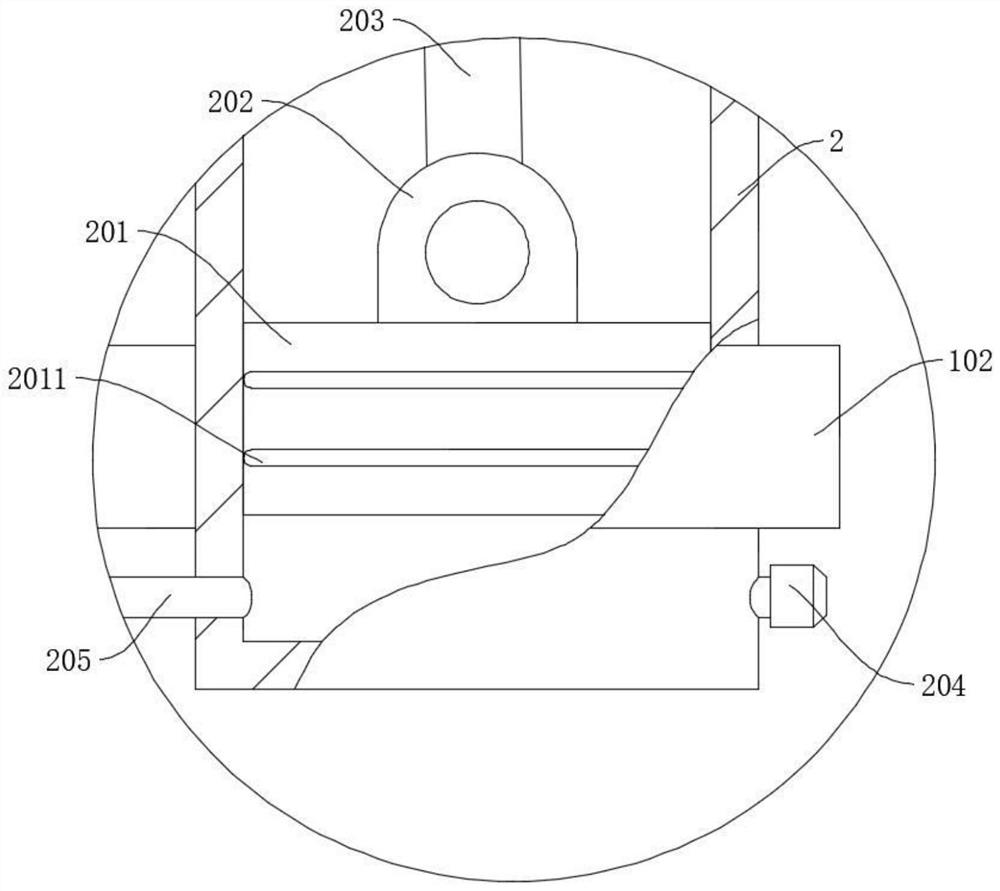
[0036] refer to Figure 1-2 , is basically the same as in Embodiment 1, furthermore, the blowing mechanism includes an air supply pipe 205 and a blowing nozzle 2051 connected to the air supply pipe 205, the air supply pipe 205 is fixedly connected to the bottom wall of the liquid storage tank 1, and the air supply pipe 205 It runs through the inner wall of the liquid storage tank 1 and extends to the outside and is fixedly connected to the booster cylinder 2. The first check valve 2052 is fixedly connected to the air supply pipe 205. There are multiple sets of spray nozzles 2051, and multiple sets of spray nozzles 2051 Evenly distributed on the air supply pipe 205, the outer wall of the liquid storage tank 1 is fixedly connected with a support plate 102, the booster cylinder 2 is fixedly connected with the support plate 102, and the bottom of the booster cylinder 2 is fixedly connected with a second one-way valve 204, a piston 201 A sealing ring 2011 is connected to the top, a...


PUM


Abstract

The invention discloses printing and dyeing equipment for textiles, and belongs to the technical field of printing and dyeing equipment. Printing and dyeing equipment for textiles comprises a liquid storage tank and a support, a blowing mechanism is arranged at the bottom of the liquid storage tank, a first rotating shaft is connected with a first belt pulley and a first roller, a second rotatingshaft is connected with a second belt pulley and a second roller, the first belt pulley is rotationally connected with the second belt pulley, and the top of the support is connected with a driving part; a third rotating shaft is rotationally connected to a rocker, a third belt pulley and a third roller are connected to the third rotating shaft, the third belt pulley is rotationally connected withthe first belt pulley, and a first positioning column is connected to the rocker; the second rotating shaft is connected with a turntable, the turntable is connected with a second positioning column,and the first positioning column is rotationally connected with the second positioning column; and a pressurizing cylinder is connected to the liquid storage tank, a piston is slidably connected intothe pressurizing cylinder, a first hinge seat is connected to the piston, and the first hinge seat is rotationally connected with the second positioning column. The rocker swings for air drying and blowing disturbance, the water content of cloth is reduced, and the coloring efficiency is improved.

Description

technical field [0001] The invention relates to the technical field of printing and dyeing equipment, in particular to a printing and dyeing equipment for textiles. Background technique [0002] With the continuous improvement and development of dyeing technology, people can print and dye different colors on the cloth to meet the aesthetic needs of different people. [0003] In the prior art, when dyeing textiles, the cloth is often put directly into the pigment pool, soaked for coloring, and then pulled out for drying and other processes. Due to the long soaking time and unsatisfactory coloring effect, multiple sets of fuels are often required The pools are side by side for repeated coloring, which not only takes up a large work space but also increases production costs. Contents of the invention [0004] The object of the present invention is to solve the defects of long coloring process and unsatisfactory effect in the prior art, and propose a printing and dyeing equip...

Claims


Application Information

Patent Timeline
Patent Type & Authority Applications(China)
IPC IPC(8): D06B3/20D06B3/34D06B23/02D06B23/04
CPCD06B3/201D06B3/206D06B3/34D06B23/02D06B23/026D06B23/04
Inventor 不公告发明人
Owner 钱炜
Why Eureka
Try Eureka