Photovoltaic-power-generation double-shaft output rotary driving device, mounting method and clearance adjusting method
A dual-axis output, rotary drive technology, applied in the direction of electromechanical devices, transmission parts, electric components, etc., can solve the problems of stuck worm helical surface, bulky, easy to wear, etc., to improve transmission efficiency and service life, Ensure transmission efficiency and increase service life
- Summary
- Abstract
- Description
- Claims
- Application Information
AI Technical Summary
Problems solved by technology
Method used
Image
Examples
Embodiment 1
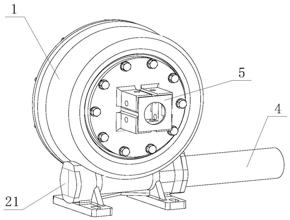
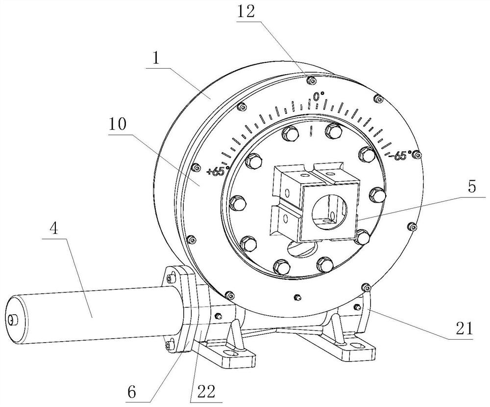
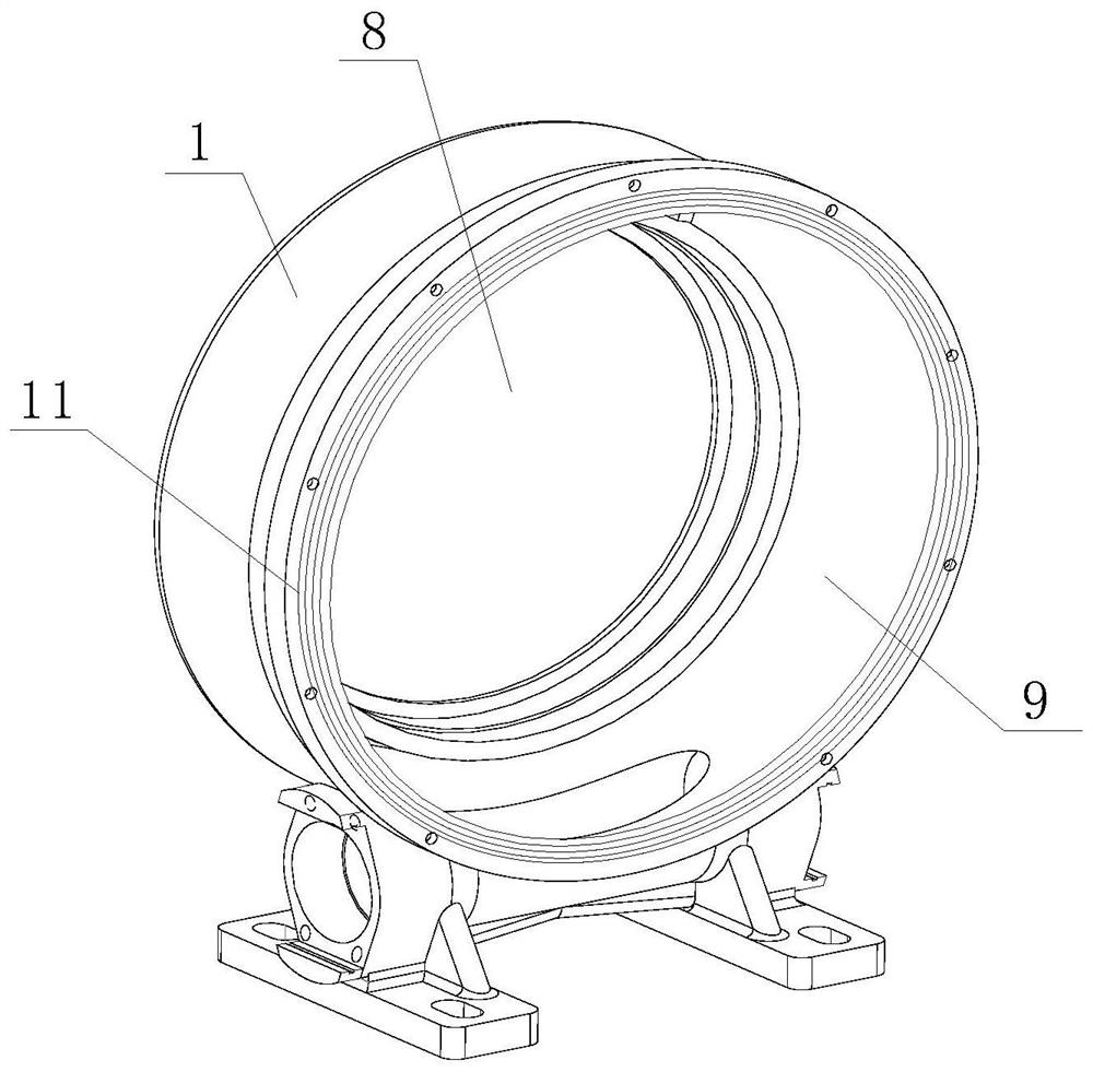
[0046] Figure 1 to Figure 11 Divide Figure 7 to Figure 9 As shown, the photovoltaic power generation double-shaft output rotary drive device includes a housing 1, a worm gear 2, a worm 3, and a drive motor 4. The housing 1 is provided with an upper cavity and a lower cavity communicating with each other;
[0047] The worm wheel 2 is symmetrically provided with a stepped shaft, and both ends of the stepped shaft on the worm wheel 2 are fixedly connected with a fixing frame 5 connected with the photovoltaic support;
[0048] The upper cavity is provided with a sealed revolving mechanism. The sealed revolving mechanism includes a sliding bearing 7, a mounting port 8, a mounting port 9, and a sealing assembly. The sliding bearing 7 is provided with two stepped shafts respectively installed on both sides of the worm wheel 2. One of the sliding bearings 7 is sealed and installed at the installation port 8 through an oil seal frame, and the other sliding bearing 7 forms a sealed fit bet...
Embodiment 2
[0056] by Figure 7 to Figure 9 As shown, since the first blocking member and the second blocking member are still in a sealed state under the action of the adjusting member, a relatively large force is required to press the two to make them move. One adjustment structure on the side shell 1 of the first 13 part, and the other adjustment structure on the side shell 1 of the blocking part two 14. Both adjustment structures include a two-way screw 17, a ratchet 18, a locking block 19, and two two-way screws 17 are respectively rotatably connected to the housing 1 at the bottom of the corresponding plugging piece 13 or plugging piece two 14, and the end of the two-way screw 17 is provided with an inner hexagon hole. The adjustment of the two-way screw 17 is realized by an inner hexagon wrench. Two wedge-shaped sliders 20 in opposite directions are connected to the screw 17 through threads. The ratchet rack 18 is fixedly connected to the corresponding blocking piece 13 or the corre...
Embodiment 3
[0058] Example 3: Installation method of the device
[0059] The installation method of the double-shaft output rotary drive device for photovoltaic power generation includes the following steps:
[0060] S1, Worm gear 2 installation: First, put the two sliding bearings 7 on both sides of the worm wheel 2, and use bolts to connect the worm wheel 2 to the fixing frame 5 of the photovoltaic bracket, and connect the worm wheel 2 and the sliding bearing 7 as a whole by a sealing accessory One side of 11 is inserted into the upper cavity;
[0061] S2, Worm 3 installation: first fix the two bearings on the worm 3 with the inner ring, then screw the end that is not connected to the drive motor 4 into the lower cavity until the distance between the two bearings and the lower cavity port is equal, Fixing the first 13 blocking member and the second blocking member 14 to the corresponding outer ring of the bearing respectively, and the adjusting member 15 penetrates the corresponding adjusting...
PUM
 Abstract
Description
Claims
Application Information
 - R&D
- Intellectual Property
- Life Sciences
- Materials
- Tech Scout
- Unparalleled Data Quality
- Higher Quality Content
- 60% Fewer Hallucinations
Browse by: Latest US Patents, China's latest patents, Technical Efficacy Thesaurus, Application Domain, Technology Topic, Popular Technical Reports.
© 2025 PatSnap. All rights reserved.Legal|Privacy policy|Modern Slavery Act Transparency Statement|Sitemap|About US| Contact US: help@patsnap.com


