Laser gyroscope testing system and testing method thereof

A technology of laser gyroscope and testing system, which is applied in the direction of measuring devices and instruments, can solve the problems of high test complexity and low test accuracy, and achieve the effects of reducing complexity, improving detection accuracy, and improving reliability

Active Publication Date: 2020-09-04
青岛君戎汇通光电科技有限公司
View PDF17 Cites 0 Cited by
  • Summary
  • Abstract
  • Description
  • Claims
  • Application Information

AI Technical Summary

Problems solved by technology

The current test system does not test the entire system of the laser gyroscope, and requires manual cooperation to provide auxiliary testing. The test accuracy is not high, the test complexity is high, and a lot of manpower and material resources are required.

Method used


Image

  • Laser gyroscope testing system and testing method thereof

Examples


Embodiment 1

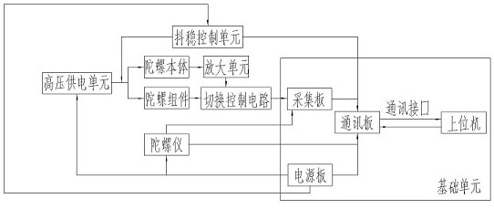
[0029] Such as figure 1 As shown, the laser gyro testing system of this embodiment is used to test and calibrate the laser gyroscope, and is characterized in that it includes three groups of test positions, which are used to test the gyroscope body, gyroscope components and gyroscope respectively, and also includes a common The base unit for the gyro body and gyro components shake stabilization control unit and high-voltage power supply unit, the amplification unit for the gyro body, the basic unit includes a host computer, a communication board, a power supply board and an acquisition board, and the host computer Connected to the communication board through the communication interface, the communication board is also electrically connected to the acquisition board, the shaking control unit and the power supply board, and the amplification unit is electrically connected to the acquisition board through the switching control circuit, and the switching control circuit is used for...

Embodiment 2

[0039] The testing method based on the laser gyroscope testing system of the present embodiment comprises the following steps:

[0040] S1. Put the product to be detected into the detection position, and select the model and type of the product to be tested on the host computer. The models are divided into three types: 50, 70 and 90, and the types are divided into three types: gyro body, gyro component, and gyroscope; Due to the different products produced by manufacturers, there are many types, but they are mainly divided into three categories: gyroscope body, gyroscope component and gyroscope.

[0041] S2. The communication board starts the work of the power board through the input information of the host computer:

[0042] If it is a gyro body, choose to switch the control circuit to the body conduction state, and at the same time select the gating control circuit to the piezoelectric conduction state, and start the high-voltage generator at the same time to provide working...


PUM


Abstract

The invention discloses a laser gyroscope testing system. The device is used for testing and calibrating the laser gyroscope and comprises three sets of test bits, which are respectively used for testing a gyroscope body, a gyroscope assembly and a gyroscope. The device also includes a stabilization control unit and a high-voltage power supply unit which are used for the gyro body and the gyro assembly, and a amplification unit which is used for the gyro body; the basic unit comprises an upper computer, a communication board, a power supply board and an acquisition board; the upper computer is connected with the communication board through a communication interface; the communication board is also electrically connected with the acquisition board, the jitter stability control unit and thepower supply board, the amplification unit is electrically connected with the acquisition board through the switching control circuit, the switching control circuit is used for switching signals input into three groups of test positions of the acquisition board, and the jitter stability control unit is electrically connected with the power supply board. The whole system greatly reduces the manpower, material resources and complexity required by the test, so that the system improves the test precision and improves the test efficiency.

Description

technical field [0001] The invention belongs to the field of instrument test equipment and its method and technology, in particular to a laser gyro test system and its method. Background technique [0002] The development of gyroscopes has always affected global navigation and positioning systems and inertial navigation systems, and they are precision navigation devices commonly used in aviation platforms or precision-guided weapons. Therefore, since the advent of laser gyroscopes, it has been used as a , smart bombs and other core components of measurement and control systems. The effectiveness of the laser gyro strapdown system is significantly improved after it is applied to rocket systems. In the past, due to the limitation of the calculation speed of the rocket machine, the real-time speed and position of the rocket could not be accurately calculated, which greatly increased the workload of ground processing data and also increased the workload of design and post-event...

Claims


Application Information

Patent Timeline
Patent Type & Authority Applications(China)
IPC IPC(8): G01C25/00
CPCG01C25/005
Inventor 谷庭军范源宋敏张珉
Owner 青岛君戎汇通光电科技有限公司
Why Eureka
Try Eureka