Partial discharge fault state identification method based on ensemble learning

A fault state, ensemble learning technology, applied in ensemble learning, testing using optical methods, character and pattern recognition, etc., to achieve superior overall performance and generalization ability, improve accuracy and stability, average recognition rate and recognition stability high sex effect

Active Publication Date: 2020-09-04
UNIV OF ELECTRONICS SCI & TECH OF CHINA +1
View PDF12 Cites 28 Cited by
  • Summary
  • Abstract
  • Description
  • Claims
  • Application Information

AI Technical Summary

Problems solved by technology

[0007] The object of the present invention is to provide a PD fault state recognition method based on integrated learning to solve the problem of high accuracy and high stability recognition of PD fault states

Method used


Image

  • Partial discharge fault state identification method based on ensemble learning
  • Partial discharge fault state identification method based on ensemble learning
  • Partial discharge fault state identification method based on ensemble learning

Examples


Embodiment 1

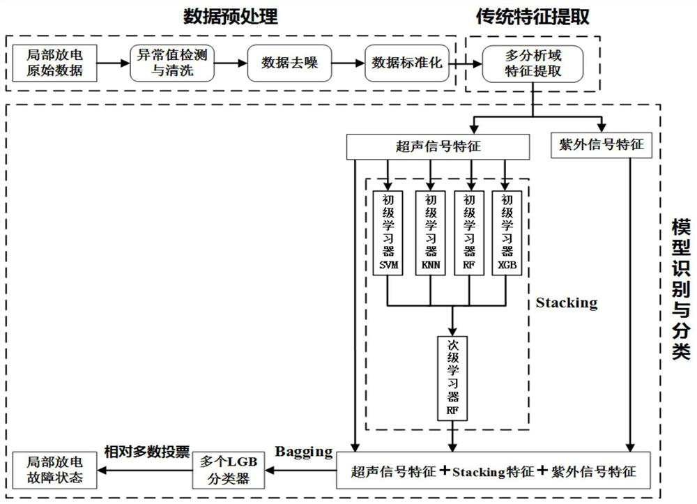
[0056] Such as figure 1 As shown, the present invention is a method for identifying partial discharge fault states based on integrated learning, which specifically includes the following steps:

[0057] Step 1: Use the partial discharge acousto-optic joint detection system to collect partial discharge signals in the actual application site, including ultrasonic signals and ultraviolet signals, and build a signal database;

[0058] Step 2: Use statistics-based box plot theory to detect and clean the abnormal values ​​of partial discharge signals;

[0059] Step 3: Use the empirical mode decomposition method to reduce the noise interference of the partial discharge signal;

[0060] Step 4: Perform data standardization processing on the denoised partial discharge signal using maximum-minimum value standardization;

[0061] Step 5: Perform multi-analysis domain feature extraction on the partial discharge signal after the standardization process in step 4, and obtain the ultrasoni...

Embodiment 2

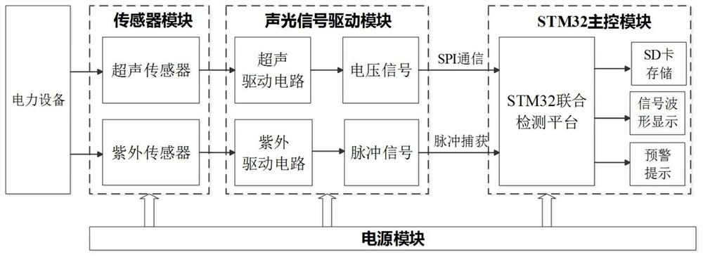
[0071] On the basis of Embodiment 1, in a preferred embodiment of the present invention, such as figure 2 As shown, the partial discharge acousto-optic joint detection system in step 1 includes a sensor module, an acousto-optic signal drive module, an STM32 main control module, and a power supply module; the sensor module includes an ultrasonic sensor and an ultraviolet sensor for collecting partial discharge process accompanying The ultrasonic signal and ultraviolet signal are converted into voltage signal and pulse signal respectively by the acousto-optic signal driver module. The voltage signal is transmitted to the STM32 main control module through SPI communication after analog-to-digital conversion. The control module collects through the pulse capture method; the STM32 main control module fuses the ultrasonic signal and the ultraviolet signal to obtain the partial discharge signal in the fault state, and completes real-time data storage, waveform display and early warni...

Embodiment 3

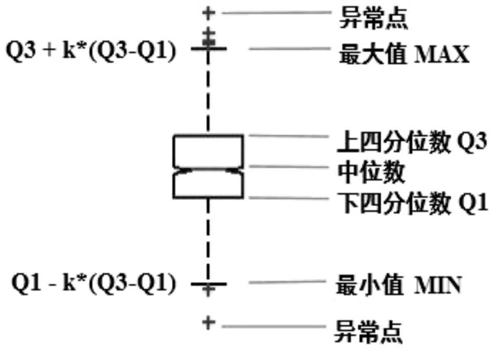
[0074] On the basis of the above embodiments, in a preferred embodiment of the present invention, the specific steps of detecting and cleaning the abnormal value of the partial discharge signal in the step 2 are as follows:

[0075] Step 21: in the signal database in step 1, separate according to the amplitude levels of the ultrasonic signal and the ultraviolet signal;

[0076] Step 22: Determine the empirical coefficient value k of the ultrasonic signal and the ultraviolet signal based on the box diagram theory;

[0077] Step 23: According to the empirical value coefficient k obtained in step 22, determine the maximum value B of the box diagram of the ultrasonic signal max1 and minimum B min1 , and the box plot maximum value B of the UV signal max2 and minimum B min2 ;

[0078] Step 24: According to the maximum value B of the box plot of the ultrasonic signal in step 23 max1 and minimum B min1 , and the box plot maximum value B of the UV signal max2 and minimum B min2...


PUM


Abstract

The invention discloses a partial discharge fault state identification method based on ensemble learning, and relates to the field of power equipment partial discharge detection and identification. The method includes: firstly, collecting a partial discharge signal through a partial discharge acoustic-optical combined detection system; obtaining raw data, carrying out data preprocessing includingabnormal value detection and cleaning, data denoising and data standardization; extracting signal features from multiple analysis domains, inputting the obtained ultrasonic signal features and ultraviolet signal features into a two-stage Stacking-Bagging ensemble learning model designed by the invention, and finally judging the partial discharge fault state of the current input signal through relative majority voting. The method is high in recognition rate of the partial discharge fault state of the power equipment, and is high in recognition stability.

Description

technical field [0001] The invention relates to the field of partial discharge detection of power equipment, in particular to a partial discharge fault state identification method based on integrated learning. Background technique [0002] It is of great significance to detect the fault state of power equipment in real time and analyze the fault development stage through the partial discharge detection method. At present, the occurrence of partial discharge is often accompanied by a variety of physical and chemical phenomena, such as the emission of electromagnetic waves and sound waves, the exchange of charges, the generation of decomposition products, and the emission of light and heat. Therefore, according to the physical, chemical and electrical characteristics of partial discharge, partial discharge detection methods are generally divided into non-electrical measurement methods and electrical measurement methods. Among them, the electrical measurement methods mainly in...

Claims


Application Information

Patent Timeline
Patent Type & Authority Applications(China)
IPC IPC(8): G06K9/00G06K9/62G01R31/12G06N20/20
CPCG01R31/1209G01R31/1218G06N20/20G06F2218/08G06F2218/12G06F18/24G06F18/253
Inventor 吴慧娟唐波邱浩宇王宇丰
Owner UNIV OF ELECTRONICS SCI & TECH OF CHINA
Why Eureka
Try Eureka