An energy-saving emergency power switching system and method

A technology of emergency power supply and switching system, which is applied in the direction of emergency power supply arrangement, power network operating system integration, information technology support system, etc. The ability to interfere, safe and fast switching, and the effect of improving reliability

Active Publication Date: 2022-03-18
SHANDONG HUATIAN ELECTRONICS SCI & TECH CO LTD
View PDF0 Cites 0 Cited by
  • Summary
  • Abstract
  • Description
  • Claims
  • Application Information

AI Technical Summary

Problems solved by technology

[0005] (1) Relays / contactors are used to switch the cold standby mode of the inverter, and the switching time can meet the national standard of 0.25s; this method has high reliability and low cost; but it cannot meet the requirement of emergency power switching time ≤ 3ms
[0006] (2) The dedicated STS (static transfer switch) method can achieve a switching time of ≤3ms; this method has a fast switching time, but the cost is high cost and low reliability. Compared with the relay / contactor method, the loss is large ( The voltage drop of the thyristor is generally 1.5V. Taking 300A as an example, the loss of the thyristor alone is as high as 1.5*300*3=1350W, while the loss of the relay / contactor is only 50*3=150W)

Method used


Image

  • An energy-saving emergency power switching system and method
  • An energy-saving emergency power switching system and method
  • An energy-saving emergency power switching system and method

Examples


Embodiment 1

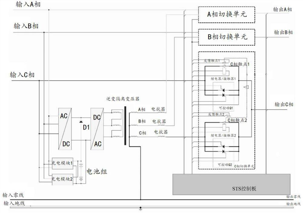
[0042] According to an embodiment of the present invention, an embodiment of an energy-saving emergency power switching system is provided, referring to figure 1 , including a switching unit controller, and a phase A switching unit, a B phase switching unit and a C phase switching unit respectively connected to the switching unit controller;

[0043] Each phase switching unit includes: a first switch assembly connected to the output end of the corresponding phase of the mains, and a second switch assembly connected to the output end of the corresponding phase of the emergency power inverter;

[0044] The first transfer switch assembly includes: a commercial power thyristor and a commercial contactor connected in parallel; the second transfer switch assembly includes: an inverter thyristor and an inverter contactor connected in parallel.

[0045] The emergency power inverter is in a hot standby state, and is connected to the second switch assembly through a reactor.

[0046] I...

Embodiment 2

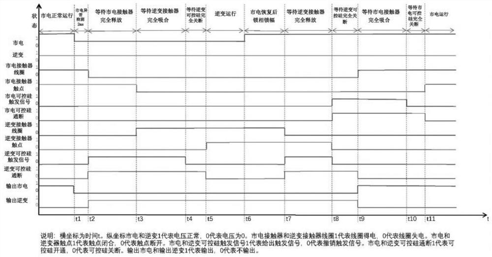
[0053] According to an embodiment of the present invention, an embodiment of an energy-saving emergency power supply switching method is provided. For specific switching logic, refer to figure 2 , including the following procedures:

[0054] Before time t1, the mains power is normal, the mains contactor is closed, and the mains power is output. At the same time, the inverter is hot standby, and maintains a phase-locked and amplitude-locked state with the mains;

[0055] At time t1, the mains power is abnormal, and at time t2 (about 2ms), the system detects that the mains power is abnormal. At this time, turn off the control signal of the mains contactor coil, turn on the trigger signal of the inverter thyristor, and turn on the inverter thyristor. During the time period t1-t2, the power supply has no output, and the load power supply is interrupted for 2ms; after the time t2, the emergency power supply inverts and outputs power supply.

[0056] At time t3, the coil of the ...


PUM


Abstract

The invention discloses an energy-saving emergency power supply switching system and method, comprising a switching unit controller, and a phase A switching unit, a B phase switching unit and a C phase switching unit respectively connected to the switching unit controller; each phase switching unit It includes: a first transfer switch assembly connected to the output end of the corresponding phase of the mains, and a second transfer switch assembly connected to the output end of the corresponding phase of the emergency power inverter; the first transfer switch assembly includes: A commercial power thyristor and a commercial power contactor; the second transfer switch assembly includes: an inverter thyristor and an inverter contactor connected in parallel. In the emergency power switch, the present invention adopts the combination of the relay / contactor that works for a long time and the silicon controlled rectifier that works for a short time, and can meet the requirement of the load for switching time ≤ 3 ms through timing control, and at the same time reduce the cost of the device , Improve reliability, reduce loss and save power.

Description

technical field [0001] The invention relates to the technical field of reliable switching of emergency power sources, in particular to an energy-saving emergency power switching system and method. Background technique [0002] The statements in this section merely provide background information related to the present invention and do not necessarily constitute prior art. [0003] As a device that provides backup power for important loads such as fire-fighting lamps and equipment, chemical equipment, smelting equipment, elevators, etc., emergency power supply has been widely used in recent years. Compared with the earlier ordinary lamps and fire fighting equipment, new applications have created new demands. Loads such as some chemical equipment and metal halide lamps have extremely strict requirements on switching time. According to some of our research, it is necessary to achieve a switching time of ≤3ms to ensure the normal operation of subsequent equipment or avoid major...

Claims


Application Information

Patent Timeline
Patent Type & Authority Patents(China)
IPC IPC(8): H02J9/06
CPCH02J9/062Y04S20/20Y02B70/30
Inventor 李波狄国顾建勇吴德祥
Owner SHANDONG HUATIAN ELECTRONICS SCI & TECH CO LTD
Why Eureka
Try Eureka