Dehumidifying and drying device for flue-cured tobacco

A drying device and flue-cured tobacco technology, applied in drying, drying machine, tobacco drying and other directions, can solve the problems of not being able to supply heat for a long time, failing to meet emission reduction standards, affecting the quality of baking, etc.

Pending Publication Date: 2020-09-08
DONGGUAN ZHENGXU ENERGY SAVING TECH
View PDF0 Cites 0 Cited by
  • Summary
  • Abstract
  • Description
  • Claims
  • Application Information

AI Technical Summary

Problems solved by technology

However, the traditional baking technology still has the following disadvantages: 1. Low energy utilization rate and serious heat loss; 2. Insufficient heat generation, which seriously affects work efficiency; 3. The structure of the heat pump baking room is complicated, and there are too many peripheral parts. There are many potential safety hazards: 4. The heating source is unstable and cannot supply heat for a long time, which affects the quality of baking; Manual monitoring; 7. The split structure takes up a lot of space and wastes materials

Method used


Image

  • Dehumidifying and drying device for flue-cured tobacco
  • Dehumidifying and drying device for flue-cured tobacco

Examples


Embodiment 1

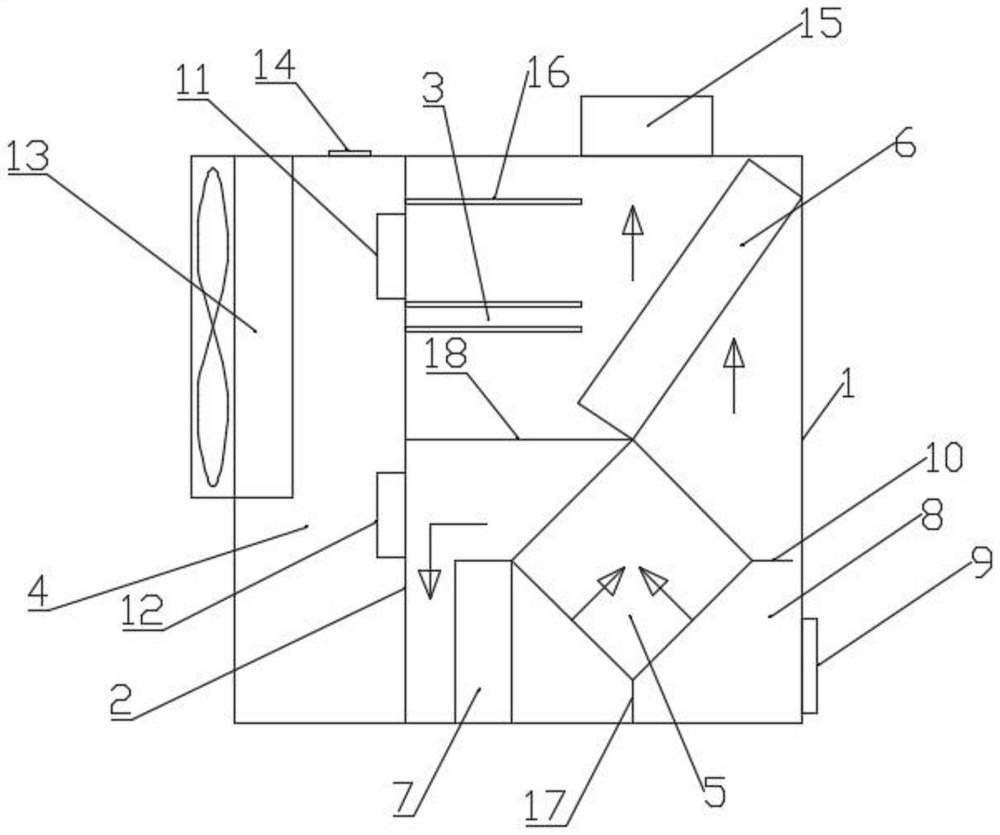
[0026] The following position and orientation descriptions are based on figure 1 The description of the distribution does not constitute a limitation.

[0027] Such as figure 1 As shown, a dehumidification and drying device for flue-cured tobacco includes a housing 1, and a first partition is arranged inside the housing 1 to divide it into a first space 3 on the right side and a second space 4 on the left side. 2. An air-to-air heat exchanger 5 is installed near the lower end of the first space 3, and the air-to-air heat exchanger 5 is set at an angle of 45° to the horizontal plane so that the heat exchange channel is inclined at 45°. The upper end of the gas-air heat exchanger 5 in the first space 3 is connected to the lower end of the condenser 6 and the upper end of the dehumidification evaporator 7 in a contact-sealed manner, respectively. A second partition 18 is arranged between the connection between the air-to-air heat exchanger 5 and the condenser 6 and the first pa...

Embodiment 2

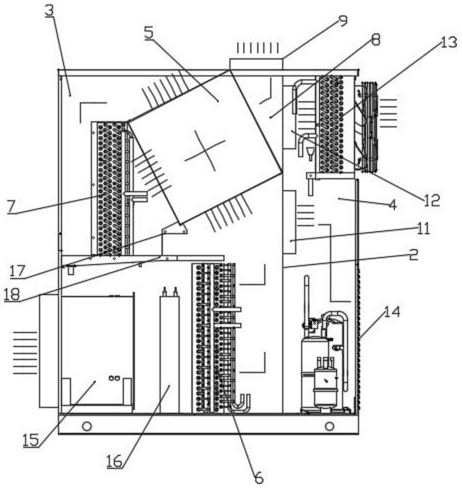
[0033] The following position and orientation descriptions are based on figure 1 The description of the distribution does not constitute a limitation.

[0034] Such as figure 2As shown, a dehumidification and drying device for flue-cured tobacco includes a housing 1, and a first partition is arranged inside the housing 1 to divide it into a first space 3 on the right side and a second space 4 on the left side. 2. The upper end of the first space 3 is provided with an air-to-air heat exchanger 5, and the air-to-air heat exchanger 5 is set at an angle of 45° to the horizontal plane so that the heat exchange channel is inclined at 45°. The upper left angle end and the right angle end of the air-to-air heat exchanger 5 in the first space 3 are respectively contact-sealed and connected to the upper end of the dehumidification evaporator 7 and the first partition 2. On the side wall, the housing 1 and the second partition 18 corresponding to the third space 8 formed between the r...


PUM


Abstract

The invention discloses a dehumidifying and drying device for flue-cured tobacco. The device comprises a shell, the interior of the shell is divided into a first space and a second space through a first partition plate. A gas-gas heat exchanger is arranged in the first space; the gas-gas heat exchanger is inclined at a certain angle relative to the horizontal plane; a condenser and a dehumidification evaporator are respectively arranged on the peripheral sides of the gas-gas heat exchanger in the first space; the peripheral sides of the gas-gas heat exchanger are respectively connected with the condenser and the dehumidification evaporator; a second partition plate is arranged between the gas-gas heat exchanger and the first partition plate; a hot air return opening is formed in the position, corresponding to one side of one air inlet of the gas-gas heat exchanger, of the shell, a small air door is arranged between the gas-gas heat exchanger and the shell in a third space, a first airdoor and a second air door are arranged on the first partition plate, and an evaporator with a fan is arranged in the second space. According to the dehumidifying and drying device for flue-cured tobacco, through reasonable structural distribution, waste heat is fully utilized, and the purpose of saving energy is achieved.

Description

technical field [0001] The invention relates to the technical field of flue-cured tobacco devices, in particular to a dehumidification and drying device for flue-cured tobacco. Background technique [0002] In today's global energy shortage, with the enhancement of energy conservation and environmental protection awareness, we strive to create a superior living environment for everyone, but high energy consumption and high pollution are also issues that cannot be ignored. From the early coal-fired baking and electric heating, these are all due to various reasons, and their disadvantages can not achieve the goals of energy saving and environmental protection advocated now. Because there is infinite energy in the atmosphere, according to the reverse Carnot cycle principle, low-temperature heat energy is absorbed from the atmosphere, and we use it rationally to evolve it into the energy we need. After years of continuous reform and innovation, the air source has been born. It...

Claims


Application Information

Patent Timeline
Patent Type & Authority Applications(China)
IPC IPC(8): A24B3/04A24B3/02A24B3/10A24B1/02F26B21/00F26B21/02F26B21/08F24H4/06
CPCA24B1/02A24B3/02A24B3/04A24B3/10F24H4/06F26B21/001F26B21/002F26B21/02F26B21/086F26B2200/22
Inventor 陈祥全陈帅荣陈宝天
Owner DONGGUAN ZHENGXU ENERGY SAVING TECH
Why Eureka
Try Eureka