A multifunctional clamping device applied to smart industry

A clamping device and multi-functional technology, applied in the field of multi-functional clamping devices, can solve the problems of incompatibility and instability of clamping, and achieve the effects of good clamping ability, convenient clamping and fixing, and health protection.

Active Publication Date: 2021-06-18
苏州悦力佳智能科技有限公司
View PDF9 Cites 0 Cited by
  • Summary
  • Abstract
  • Description
  • Claims
  • Application Information

AI Technical Summary

Problems solved by technology

[0004] Intelligent industrial technology is used in various production links today. For example, in the process of processing items, it is necessary to clamp and fix the items and then process them. The traditional fixing method is to use the screw to drive the clamping block to move the items. And it adopts the manual driving method. Later, with the development of the machinery industry, the manual driving method was changed to the mechanical driving form, but for items of different thicknesses, the clamping will appear unsuitable and unstable. situation arises

Method used


Image

  • A multifunctional clamping device applied to smart industry
  • A multifunctional clamping device applied to smart industry
  • A multifunctional clamping device applied to smart industry

Examples


Embodiment 1

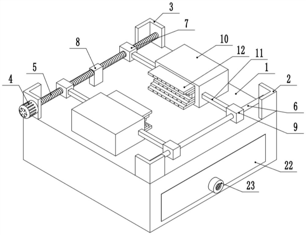
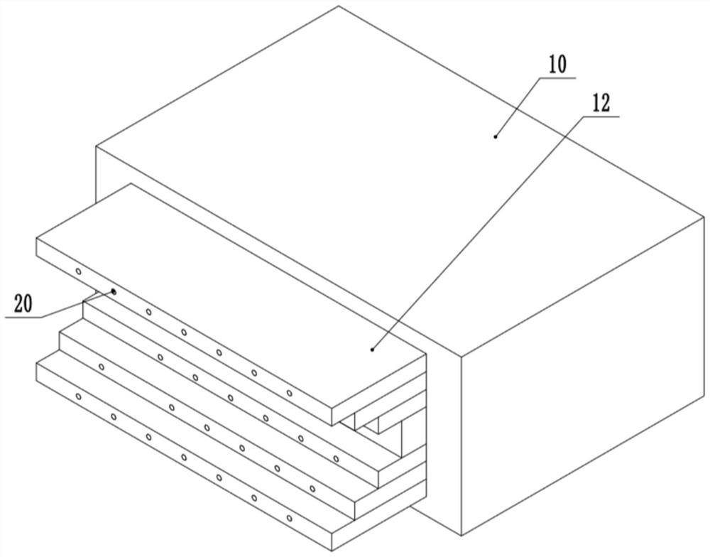
[0028] see Figure 1-6 , a multi-functional clamping device applied to smart industry, including a workbench 1, two first end seats 2 and two second end seats 3 are respectively fixed on the two ends of the top of the workbench 1, two first end seats 3 The guide rod 6 is fixedly connected between the end bases 2, and the drive screw 5 is fixedly connected between the two second end bases 3. One of the second end bases 3 is fixedly connected to the first drive motor 4, and the output shaft of the first drive motor 4 is connected to the The drive screw 5 is coaxially fixedly connected, two clamping seats 10 are slidably provided on the workbench 1, and self-adaptive clamping devices are arranged on the two clamping seats 10, and the external screw thread of the drive screw 5 is connected with a first The moving block 7, the outer sliding connection of the guide bar 6 is connected with the second moving block 9, and the connecting rod 11 is fixedly connected between the clamping ...

Embodiment 2

[0038] see Figure 1-6 , the other content of this embodiment is the same as that of Embodiment 1, the difference is that: the middle part of the drive screw 5 is connected to the partition block 8 by rotation, the partition block 8 is fixedly connected to the workbench 1, and the drive screw rods 5 on both sides of the partition block 8 The direction of the threads is reversed.

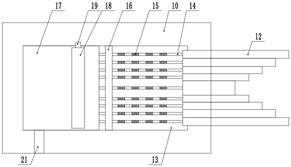
[0039] In the implementation process of the present invention, the first drive motor 4 is started to drive the two clamping seats 10 to move closer together to clamp the article. At the same time, the corresponding clamping plate 12 is pushed into the clamping seat 10, and the clamping plate 12 When moving, the conductive block 15 will pass through the fixed rod 16 and contact the conductive jacket 28, thereby generating a signal. According to this signal, the electromagnet 31 on the drive rod 29 on the side of the corresponding unmoved splint 12 is de-energized, and the The driving gear 26 is locked,...


PUM


Abstract

The invention discloses a multifunctional clamping device applied to smart industry, relates to the technical field of smart industry, and includes a workbench, two first end seats and two second end seats are respectively fixed on the two ends of the top of the workbench , the guide rod is fixedly connected between the two first end seats, the drive screw is fixedly connected between the two second end seats, the second end seat is fixedly connected with the first drive motor, and the output shaft of the first drive motor is coaxial with the drive screw Fixed connection, the present invention can automatically adjust the clamping height according to the size of the clamped item by setting an adaptive clamping device, so that the clamped item can be stably clamped without affecting the processing operation. The negative pressure fan can absorb the dust and gas generated during the processing of the clamped items, thereby protecting the health of the operator. Class-sized items are clamped and fixed.

Description

technical field [0001] The invention relates to the technical field of intelligent industry, in particular to a multifunctional clamping device applied in intelligent industry. Background technique [0002] Intelligent industry is a new industrial system in which physical equipment, computer network, and human brain intelligence are integrated and trinity. The realization of intelligent industry is based on the penetration and application of Internet of Things technology, and combined with future advanced manufacturing technology to form a new intelligent manufacturing system. Therefore, the key technology of intelligent industry lies in the Internet of Things technology. [0003] The basis of industrialization is automation. The field of automation has been developed for nearly a hundred years, and the theory and practice have been very perfect. Especially with the continuous rise of modern large-scale industrial production automation and the increasingly complex operatio...

Claims


Application Information

Patent Timeline
Patent Type & Authority Patents(China)
IPC IPC(8): B25B11/00B08B5/04
CPCB08B5/04B25B11/00
Inventor 顾家伟
Owner 苏州悦力佳智能科技有限公司
Why Eureka
Try Eureka