An electric cylinder lifting device and a tile conveying device

A lifting device and electric cylinder technology, applied in the direction of lifting devices, conveyors, lifting frames, etc., can solve the problems of low positioning accuracy, non-adjustable speed, difficult adjustment of lifting angle steel lifting stroke, etc., to achieve accurate parking and high positioning accuracy , the effect of convenient adjustment

Active Publication Date: 2022-05-24
GUANGDONG SUMMIT CERAMIC CO LTD +2
View PDF13 Cites 0 Cited by
  • Summary
  • Abstract
  • Description
  • Claims
  • Application Information

AI Technical Summary

Problems solved by technology

[0003] At present, two kinds of lifting devices are commonly used on the market, one is a lifting device with a cylinder as a driving mechanism, such as: CN207566296U discloses a roller table lifting and turning machine, including a frame, and a ceramic tile bracket installed on the frame. The roller group and the driving device for driving the rotation of the roller group also include a rotating pallet arranged on the roller group for placing tiles, which is arranged at the bottom of the frame and can be vertically The lifting frame for vertical lifting movement, the rotating motor for driving the horizontal rotation of the rotating pallet, the lifting guide shaft for driving the vertical lifting movement of the lifting frame, and the lifting guide shaft for driving the lifting and lowering movement of the lifting guide shaft. The drive assembly, through the combination of roller rod group, rotating pallet, drive cylinder, pendulum mechanism, eccentric wheel, lifting guide shaft and other accessories, realizes the function of conveying and rotating U-turn for large-sized ceramic tiles, but the lifting U-turn of the roller table The disadvantages of using the driving cylinder for the lifting drive assembly of the machine are: 1. The speed at which the driving cylinder drives the lifting frame cannot be adjusted; 2. Due to the heavy weight of the large-sized tiles, the stopping position of the driving cylinder is not accurate. ; 3, the positioning accuracy of the drive cylinder is low
[0004] The other is a lifting device with a motor crank wheel as a driving mechanism. As CN201834707U discloses a conjoined lifting device for producing ceramic tiles, the lifting device is assembled on the platform frame, and the lifting device includes a lifting device Angle steel and connecting rod mechanism, wherein the reducer is installed on the platform frame, the crank wheel is installed on the transmission shaft of the reducer, and the connecting rod mechanism is at least one group, which is assembled on the platform frame by lifting the angle steel, and the connecting rod The mechanism includes a joint bearing and a connecting rod. One end of the connecting rod is hinged to the crank wheel, the other end is hinged to one end of the crank rod, and the other end of the crank rod is connected to the deflection shaft. On the angle steel, one end of the crank arm is connected to the deflection shaft, the other end is connected to the adjustment plate through a joint bearing, and the lifting bracket is installed on the adjustment plate through a screw rod. The type lifting mechanism can lift the bricks before they enter the roller table, and then transfer them to the brick feeding roller table at a faster speed, and at the same time as it rises, the subsequent bricks can move forward, saving a lot of action time, and It will not cause brick collision, but the disadvantages of using the motor crank wheel as the driving mechanism are: 1. The speed at which the motor crank wheel drives the lifting angle steel is not adjustable; 2. The lifting stroke of the lifting angle steel is difficult to adjust; 3. The motor crank wheel stop position is not accurate and the positioning accuracy is low

Method used


Image

  • An electric cylinder lifting device and a tile conveying device
  • An electric cylinder lifting device and a tile conveying device
  • An electric cylinder lifting device and a tile conveying device

Examples


Embodiment Construction

[0024] In order to make the purpose, technical solutions and advantages of the present invention clearer, the present invention will be further described in detail below in conjunction with the embodiments, but the claimed scope of the present invention is not limited to the following specific embodiments.

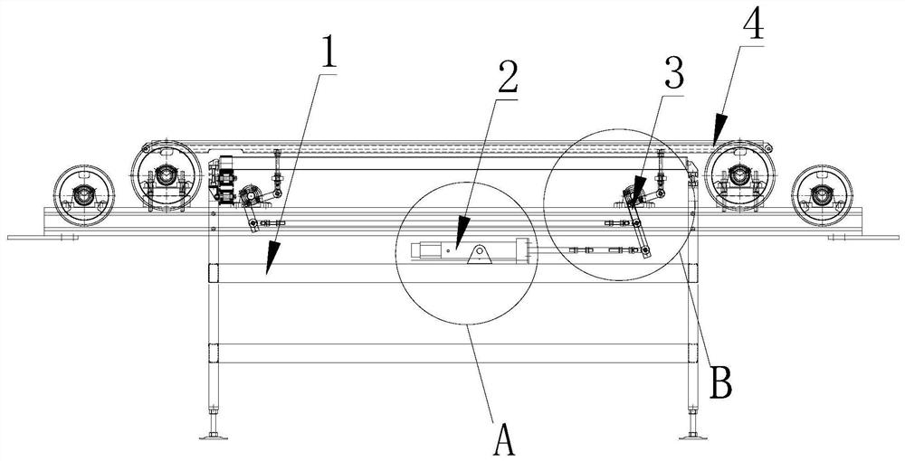
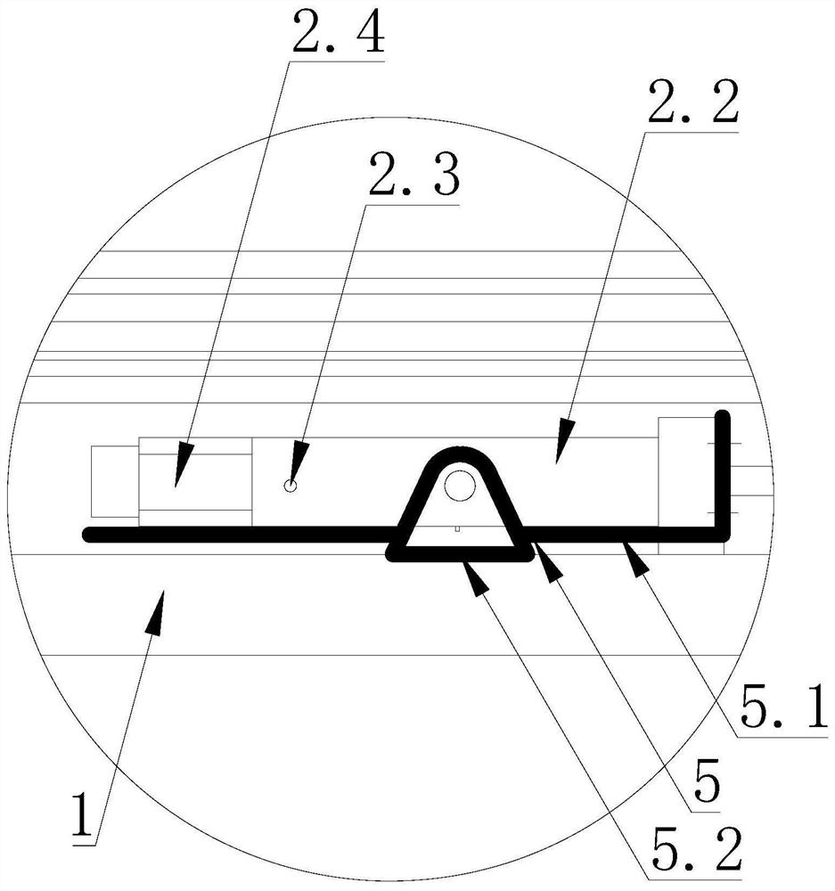
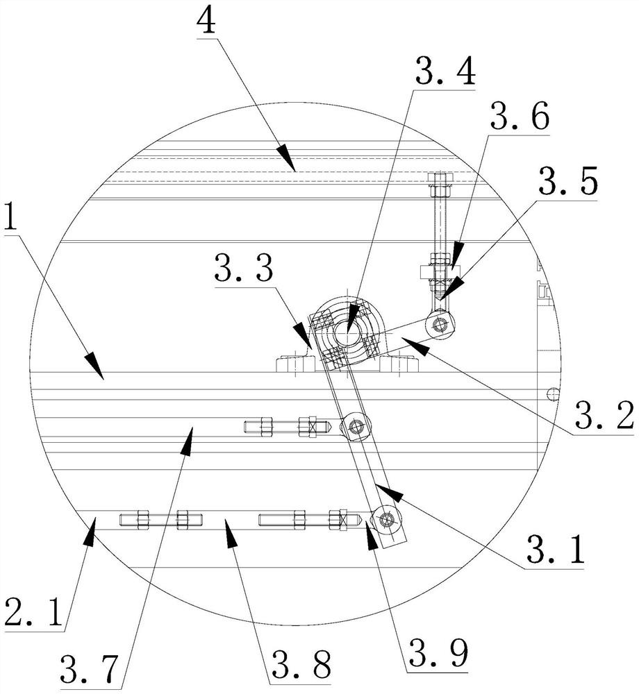
[0025] refer to Figure 1-3, this embodiment discloses an electric cylinder lifting device, including an industrial computer, a rack 1, an electric cylinder 2, a link mechanism 3 and a lifting bracket 4, the electric cylinder 2 and the link mechanism 3 are arranged on the rack 1, and the industrial control The machine is electrically connected with the electric cylinder 2, the piston rod 2.1 of the electric cylinder 2 is connected with the connecting rod mechanism 3, the connecting rod mechanism 3 is connected with the lifting bracket 4, the piston rod 2.1 of the electric cylinder 2 drives the connecting rod mechanism 3 to act, and the connecting rod mechanism 3 Drive the ...


PUM


Abstract

The invention discloses an electric cylinder lifting device and a ceramic tile transmission device. The electric cylinder lifting device includes an industrial computer, a frame, an electric cylinder, a connecting rod mechanism and a lifting bracket, the electric cylinder and the connecting rod mechanism are arranged on the frame, and the industrial computer It is electrically connected with the electric cylinder, the piston rod of the electric cylinder is connected with the connecting rod mechanism, the connecting rod mechanism is connected with the lifting bracket, the piston rod of the electric cylinder drives the connecting rod mechanism, and the connecting rod mechanism drives the lifting bracket for lifting action. The beneficial effects obtained by the present invention: the industrial computer controls the piston rod of the electric cylinder to expand and contract at different speeds, realizes the adjustable lifting speed of the lifting bracket, and achieves a flexible lifting effect, and the electric cylinder is used as the power source for driving the lifting bracket, and the lifting bracket stops. Accurate, high positioning accuracy, the accuracy reaches 0.01mm, and the lifting stroke of the lifting bracket is adjustable.

Description

technical field [0001] The invention relates to the technical field of tile production equipment, in particular to an electric cylinder lifting device and a tile conveying device. Background technique [0002] In the ceramic tile industry, in the process of making ceramic tiles, it needs to go through multiple processes to prepare. When going through multiple processes, due to the limitation of the site of the ceramic tile factory, the conveyed tiles often need to be transferred according to the set restrictions of the production line. The position of the steering transmission needs to be provided with a lifting device to achieve the steering effect. [0003] At present, two kinds of lifting devices are commonly used in the market, one is a lifting device using a cylinder as a driving mechanism, such as: CN207566296U discloses a roller table lifting and turning machine, which includes a frame, and a lifting device for tiles installed on the frame. The roller bar group and t...

Claims


Application Information

Patent Timeline
Patent Type & Authority Patents(China)
IPC IPC(8): B65G49/08B65G47/244B66F7/16B66F7/28
CPCB65G49/08B65G47/244B66F7/16B66F7/28B65G2201/022
Inventor 叶德林简润桐魏心平黄国华
Owner GUANGDONG SUMMIT CERAMIC CO LTD
Why Eureka
Try Eureka