Utilization device of integral natural gas compressor energy-saving technique

A natural gas and compressor technology, applied in the field of integrated natural gas compressor energy-saving technology utilization devices, can solve problems such as corrosion of the rear pulley, easy dust contamination of the pulley, etc., and achieve the effect of convenient cleaning

Inactive Publication Date: 2020-09-08
林威臻
View PDF0 Cites 2 Cited by
  • Summary
  • Abstract
  • Description
  • Claims
  • Application Information

AI Technical Summary

Problems solved by technology

[0003] When the integrated natural gas compressor energy-saving technology utilization device is actually used, the exhaust gas discharged during the exhaust gas discharge process will directly cause the fan blade

Method used


Image

  • Utilization device of integral natural gas compressor energy-saving technique
  • Utilization device of integral natural gas compressor energy-saving technique
  • Utilization device of integral natural gas compressor energy-saving technique

Examples


Embodiment 1

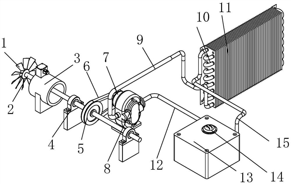
[0028] see figure 1 , the present invention provides an integrated natural gas compressor energy-saving technology utilization device through improvement, including fan blade 1, the inner middle part of fan blade 1 is fixed with transmission shaft 2, and the middle part of the outer diameter surface of transmission shaft 2 and the right end are fixed with shaft seats 4. The outer diameter surface of the transmission shaft 2 is sleeved with the driving pulley 5 near the right end of the middle part, and the outer diameter surface of the driving pulley 5 rotates synchronously with the driven pulley 7 through the timing belt 6, and the inner right end of the driven pulley 7 is connected with the circulation pump 8. The connecting shaft on the left side is connected by rotation. The lower end of the front end of the circulation pump 8 is connected to the copper pipe 10 through the drain pipe 9. The outer diameter surface of the copper pipe 10 is fixed with fins 11. The lower end of...

Embodiment 2

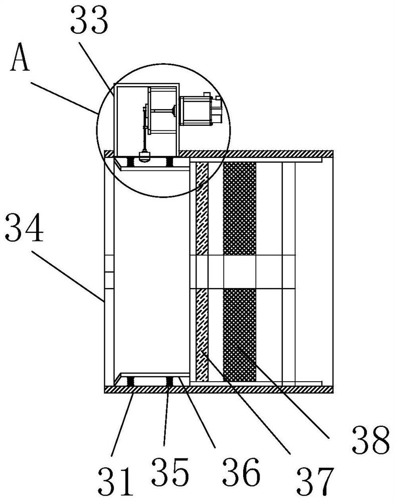
[0033] The present invention provides an integrated natural gas compressor energy-saving technology utilization device through improvement. The middle part of the primary effect filter 37 and the high-efficiency filter 38 is provided with a through hole to facilitate the stable passing of the transmission shaft 2; the middle part of the top of the box body 331 is provided There is a sealing cover, and the sealing cover is fixed with the box body 331 by bolts, which is convenient for internal inspection and maintenance; eight groups of springs 35 are arranged, and the eight groups of springs 35 are distributed in a ring, which is convenient for the stable vibration of the inner tube 36.

[0034] The present invention provides an integral natural gas compressor energy-saving technology utilization device through improvement, and its working principle is as follows;

[0035] First, when the equipment needs to be used, first place the equipment at the position where it needs to be ...


PUM


Abstract

The invention discloses a utilization device of an integral natural gas compressor energy-saving technique. The utilization device comprises a fan blade, a driving shaft, an efficient air filter, a shaft seat, a driving pulley, a synchronous belt, a driven pulley, a circulating pump, a drain pipe, a copper pipe, fins, a pumping pipe, a water tank, an injection port and an access pipe. According tothe utilization device, the efficient air filter is installed on the right end of the fan blade, the driving shaft passes through the efficient air filter, the rotation of the driving shaft cannot beinfluenced, and additionally, a primary filter screen and an efficient filter screen are installed in the efficient air filter, so that tail gas is filtered, and mixed dust can be blocked; a dust removal mechanism is installed on the left end of the inner top of the efficient air filter, a reciprocating driving mechanism is arranged in the dust removal mechanism, and the mechanism is controlled by an independent motor, so that an inner pipe is stricken in a reciprocating mode by a bottom impact block, dust attached to the inner wall of the inner pipe conveniently falls off, and the manual cleaning is facilitated.

Description

technical field [0001] The invention relates to the field related to the utilization of energy-saving technology of natural gas compressors, in particular to an integrated energy-saving technology utilization device of natural gas compressors. Background technique [0002] The integral natural gas compressor uses natural gas as the power gas, and the output mechanical energy compresses the low-pressure intake air into a high-pressure output gas power machine. When the natural gas compressor is used, a large amount of heat is generated during the gas compression process, and special equipment is required. External cooling equipment is used for cooling, but in the cooling process, a large amount of electric energy is consumed and resources are wasted, and a special natural gas compressor energy-saving technology utilization device is required. The natural gas compressor energy-saving technology utilization device can compress the exhaust gas generated by the wind energy The ci...

Claims


Application Information

Patent Timeline
IPC IPC(8): F01K25/14F01D15/08F04B17/00B01D46/12B01D46/00F28F21/08F28F1/24
CPCF01K25/14F01D15/08F04B17/00B01D46/12F28F21/085F28F1/24B01D46/64
Inventor 林威臻
Owner 林威臻
Why Eureka
Try Eureka