A pulsating displacement vacuum dryer device

A vacuum dryer and vacuum pumping technology, which is applied in non-progressive dryers, drying gas arrangement, dryers, etc., can solve the problem that water vapor cannot be discharged well, materials are dry and heated unevenly, and gas supply methods are uneven. Correctness and other issues to achieve the effect of shortening the start-up time, uniform distribution, and improving drying efficiency

Active Publication Date: 2021-05-25
CHANGZHOU AOKAI DRYING EQUIP
View PDF5 Cites 0 Cited by
  • Summary
  • Abstract
  • Description
  • Claims
  • Application Information

AI Technical Summary

Problems solved by technology

[0003] 1. When the existing drying equipment is in use: in order to make the drying more efficient, the inside of the drying tank will be vacuumed, but after vacuuming, because there is no carrier, the water vapor after drying cannot be directly discharged, which affects the drying process. In addition, it takes a certain amount of time to evacuate the inside of the drying tank through a vacuum pump, which affects the efficiency of material drying;
[0004] 2. When the existing drying equipment is in use: the gas supply method is incorrect, and the whole-process supply method is adopted, so that the water vapor inside the accumulated material cannot be discharged well;
[0005] 3. When the existing drying equipment is in use, it cannot ensure that the gas used for drying passes through the material evenly, and the moisture in the material is discharged, so that the drying and heating of the material are uneven;

Method used


Image

  • A pulsating displacement vacuum dryer device
  • A pulsating displacement vacuum dryer device
  • A pulsating displacement vacuum dryer device

Examples


Embodiment

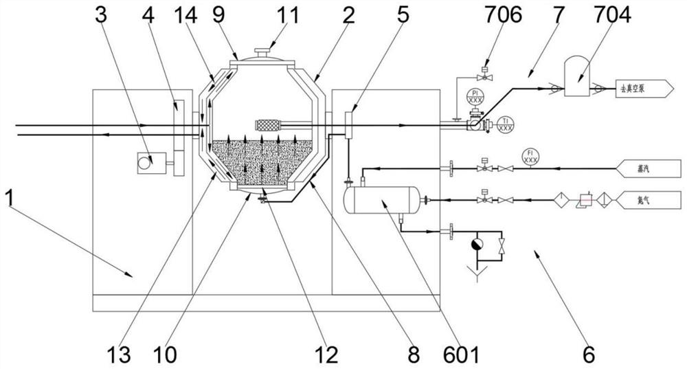
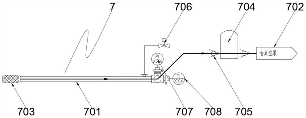
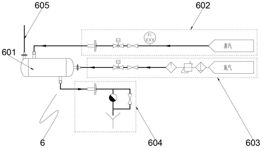
[0058] Example: such as Figure 1-8 As shown, a pulsating displacement vacuum dryer device includes a frame 1, a rotary tank body 2, a rotary air guiding device 5, an air supply mechanism 6, an exhaust mechanism 7 and a control system;

[0059] The rotary tank body 2 is supported in the air by the frame 1, and one end of the rotary tank body 2 connected to the frame 1 drives the rotary tank body 2 to rotate through the transmission motor 3, and the rotation speed of the rotary tank body 2 is reduced by the reducer 4, and the reducer 4 Mesh connection with the output gear of the transmission motor 3, the reducer 4 is used to reduce the speed of the rotary tank 2, so as to ensure that the materials inside the rotary tank 2 will not be unable to turn over by themselves due to centrifugal movement, which will affect the drying effect of the materials , the rotational speed of the rotary tank body 2 is less than 10r / min, the other end of the rotary tank body 2 connected to the fram...


PUM


Abstract

The invention discloses a pulsating displacement vacuum dryer device, which belongs to the technical field of material drying. The rotary tank body is supported in the air by a frame, and a rotary air guiding device is arranged at one end of the rotary tank body connected to the frame , the rotary air guide device is connected to the rotary tank body and the air supply mechanism, and the end of the rotary tank body close to the rotary air guide device is also provided with an exhaust mechanism for exhausting and vacuuming. The invention is scientific and reasonable, safe and convenient to use , using the cavity of the first jacket and the heat source to heat the inside of the rotary tank to realize indirect heating and avoid polluting the material. The materials in the tank are in convective contact to realize heat exchange. At the same time, the gas after heat exchange is discharged through the exhaust mechanism, and the heated inert gas is used as the carrier for the water vapor discharge after the material is dried, so as to improve the drying efficiency of the material.

Description

technical field [0001] The invention relates to the technical field of material drying, in particular to a pulse displacement vacuum dryer device. Background technique [0002] In the pharmaceutical, liquid crystal, chemical, food and other industries, the processing and production of raw materials is inseparable from the drying of raw materials, and there are various types of drying equipment for raw material drying, and for the existing technology, raw material drying equipment There are the following problems when using: [0003] 1. When the existing drying equipment is in use: in order to make the drying more efficient, the inside of the drying tank will be vacuumed, but after vacuuming, because there is no carrier, the water vapor after drying cannot be directly discharged, which affects the drying process. In addition, it takes a certain amount of time to evacuate the inside of the drying tank through a vacuum pump, which affects the efficiency of material drying; ...

Claims


Application Information

Patent Timeline
Patent Type & Authority Patents(China)
IPC IPC(8): F26B5/04F26B11/04F26B21/00F26B23/10F26B25/00
CPCF26B5/04F26B11/0445F26B21/001F26B21/003F26B21/004F26B23/10F26B25/00F26B25/007
Inventor 杨小荣
Owner CHANGZHOU AOKAI DRYING EQUIP
Why Eureka
Try Eureka